- Home
- Blog
- Oracle RAC
- Oracle RAC Tutorial

Oracle Real Application clusters allow multiple instances to access a single database, the instances will be running on multiple nodes. In a standard Oracle configuration, a database can only be mounted by one instance but in a RAC environment, many instances can access a single database.
This tutorial gives you an overview and talks about the fundamentals of Oracle RAC.
Oracle RAC Tutorial - Table of Contents
- Oracle RAC Architecture
- RAC Components
- Disk Architecture
- Oracle Kernel Components
- RAC Background Processes
- Oracle RAC Daemons and Processes
- RAC Installation
- RAC Administration
- RAC Performance
- AWR Section
- Reading a Block From the Cache
- Reading a Block From Disk
- Debugging CRS and GSD
| If you would like to Enrich your career and get an Oracle RAC certified professional, enroll in our “Oracle RAC Online Training” Course. This course will help you to achieve excellence in this domain. |
Oracle RAC Architecture
Oracle’s RAC is heavily dependent on an efficient, high reliable high-speed private network called the interconnect, make sure when designing a RAC system that you get the best that you can afford.
The table below describes the difference between a standard oracle database (single instance) and a RAC environment:
| Component | Single Instance Environment | RAC Environment |
| SGA | An instance has its own SGA | Each instance has its own SGA |
| Background processes | The instance has its own set of background processes | Each instance has its own set of background processes |
| Datafiles | Accessed by only one instance | Shared by all instances (shared storage) |
| Control Files | Accessed by only one instance | Shared by all instances (shared storage) |
| Online Redo Logfile | Dedicated for write/read to only one instance | Only one instance can write but other instances can be read during recovery and archiving. If an instance is shut down, log switches by other instances can force the idle instance to redo logs to be archived |
| Archived Redo Logfile | Dedicated to the instance | Private to the instance but other instances will need access to all required archive logs during media recovery |
| Flash Recovery Log | Accessed by only one instance | Shared by all instances (shared storage) |
| Alert Log and Trace Files | Dedicated to the instance | Private to each instance, other instances never read or write to those files. |
| ORACLE_HOME | Multiple instances on the same server accessing different databases cause the same executable files | Same as single instance plus can be placed on a shared file system allowing a common ORACLE_HOME for all instances in a RAC environment. |
RAC Components
The major components of an Oracle RAC system are:
- Shared disk system
- Oracle Clusterware
- Cluster Interconnects
- Oracle Kernel Components.
The below diagram describes the basic architecture of the Oracle RAC environment:
.png&w=1200&q=75)
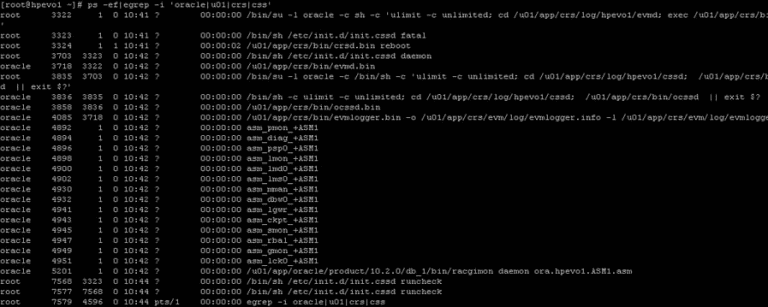
Here is a list of processes running on a freshly installed RAC:
Disk Architecture
With today’s SAN and NAS disk storage systems, sharing storage is fairly easy and is required for a RAC environment, you can use the below storage setups
- SAN (Storage Area Networks): generally using fiber to connect to the SAN
- NAS ( Network Attached Storage): generally using a network to connect to the NAS using either NFS, ISCSI
- JBOD: direct-attached storage, the old traditional way and still used by many companies as a cheap option.
All of the above solutions can offer multi-pathing to reduce SPOFs within the RAC environment, there is no reason not to configure multi-pathing as the cost is cheap when adding additional paths to the disk because most of the expense is paid when out when configuring the first path, so an additional controller card and network/fiber cables are all that is a need.
The last thing to think about is how to set up the underlining disk structure this is known as a raid level, there are about 12 different raid levels that I know of, here are the most common ones raid 0 (Striping) A number of disks are concatenated together to give the appearance of one very large disk.
Advantages
- Improved performance
- Can Create very large Volumes
Disadvantages
- Not highly available (if one disk fails, the volume fails)
- raid 1 (Mirroring) A single disk is mirrored by another disk if one disk fails the system is unaffected as it can use its mirror.
Advantages
- Improved performance
- Highly Available (if one disk fails the mirror takes over)
Disadvantages
- Expensive (requires double the number of disks)
raid 5- Raid stands for Redundant Array of Inexpensive Disks, the disks are striped with parity across 3 or more disks, the parity is used in the event that one of the disks fails, the data on the failed disk is reconstructed by using the parity bit.
Advantages
- Improved performance (read-only)
- Not expensive
Disadvantages
- Slow write operations (caused by having to create the parity bit)
There are many other raid levels that can be used with a particular hardware environment for example EMC storage uses the RAID-S, HP storage uses Auto RAID, so check with the manufacture for the best solution that will provide you with the best performance and resilience.
Once you have your storage attached to the servers, you have three choices on how to set up the disks
- Raw Volumes: normally used for performance benefits, however, they are hard to manage and backup
- Cluster FileSystem: used to hold all the Oracle datafiles can be used by Windows and Linux, its not used widely
- AUTOMATIC STORAGE MANAGEMENT (ASM): Oracle choice of storage management, its a portable, dedicated, and optimized cluster filesystem.
Oracle Clusterware software is designed to run Oracle in a cluster mode, it can support you to 64 nodes, it can even be used with a vendor cluster like Sun Cluster.
The Clusterware software allows nodes to communicate with each other and forms the cluster that makes the nodes work as a single logical server. The software is run by the Cluster Ready Services (CRS) using the Oracle Cluster Registry (OCR) that records and maintains the cluster and node membership information and the voting disk which acts as a tiebreaker during communication failures.
Consistent heartbeat information travels across the interconnect to the voting disk when the cluster is running.
The CRS has four components:
- OPROCd: Process Monitor Daemon
- CRSd: CRS daemon, the failure of this daemon results in a node being reboot to avoid data corruption
- OCSSd: Oracle Cluster Synchronization Service Daemon (updates the registry)
- EVMd: Event Volume Manager Daemon.
The OPROCd daemon provides the I/O fencing for the Oracle cluster, it uses the hang check timer or watchdog timer for the cluster integrity. It is locked into memory and runs as a real-time process, failure of this daemon results in the node being rebooted.
Fencing is used to protect the data, if a node were to have problems fencing presumes the worst and protects the data thus restarts the node in question, it's better to be saved than sorry.
The CRS process manages resources such as starting and stopping the services and failover of the application resources, it also spawns separate processes to manage application resources. CRS manages the OCR and stores the current know state of the cluster, it requires a public, private, and VIP interface in order to run.
OCSSd provides synchronization services among nodes, it provides access to the node membership and enables basic cluster services, including cluster group services and locking, failure of this daemon causes the node to be rebooted to avoid split-brain situations.
The below functions are covered by the OCSSd
- CSS provides basic Group Services Support, it is a distributed group membership system that allows applications to coordinate activities to archive a common result.
- Group services use vendor Clusterware group services when it is available.
- Lock services provide the basic cluster-wide serialization locking functions, it uses the First In, First Out (FIFO) mechanism to manage to lock
- Node services use OCR to store data and updates the information during reconfiguration, it also manages the OCR data which is static otherwise.
The last component is the Event Management Logger, which runs the EVMd process. The daemon spawns a process called evmlogger and generates the events when things happen. The vlogger spawns new children's processes on demand and scans the callout directory to invoke callouts. Death of the EVMd daemon will not halt the instance and will be restarted.
[ Check out Overview On Oracle RAC Resource Mastering ]
Quick Recap
| CRS Process | Functionality | Failure of the Process | Run AS |
| OPROCd – Process Monitor | provides basic cluster integrity services | Node Restart | root |
| EVMd – Event Management | spawns a child process event logger and generates callouts | Daemon automatically restarted, no node restart | oracle |
| OCSSd – Cluster Synchronization Services | basic node membership, group services, basic locking | Node Restart | oracle |
| CRSd – Cluster Ready Services | resource monitoring, failover, and node recovery | Daemon restarted automatically, no node restart | root |
The cluster-ready services (CRS) is a new component in 10g RAC, it is installed in a separate home directory called ORACLE_CRS_HOME. It is a mandatory component but can be used with a third party cluster (Veritas, Sun Cluster), by default it manages the node membership functionality along with managing regular RAC-related resources and services
RAC uses a membership scheme, thus any node wanting to join the cluster is to become a member. RAC can evict any member that seems like a problem, its primary concern is protecting the data. You can add and remove nodes from the cluster and the membership increases or decrease when network problems occur membership becomes the deciding factor on which part stays as the cluster and what nodes get evicted, the use of a voting disk is used which I will talk about later.
The resource management framework manages the resources to the cluster (disks, volumes), thus you can have only had one resource management framework per resource. Multiple frameworks are not supported as it can lead to undesirable effects.
The Oracle Cluster Ready Services (CRS) uses the registry to keep the cluster configuration, it should reside on shared storage and access to all nodes within the cluster. This shared storage is known as the Oracle Cluster Registry (OCR) and it's a major part of the cluster, it is automatically backed up (every 4 hours) by the daemons plus you can manually back it up. The OCSSd uses the OCR extensively and writes the changes to the registry
The OCR keeps details of all resources and services, it stores name and value pairs of information such as resources that are used to manage the resource equivalents by the CRS stack. Resources with the CRS stack are components that are managed by CRS and have the information on the good/bad state and the callout scripts. The OCR is also used to supply bootstrap information ports, nodes, etc, it is a binary file.
The OCR is loaded as cache on each node, each node will update the cache then only one node is allowed to write the cache to the OCR file, the node is called the master. The Enterprise manager also uses the OCR cache, it should be at least 100MB in size. The CRS daemon will update the OCR about the status of the nodes in the cluster during reconfigurations and failures.
The voting disk (or quorum disk) is shared by all nodes within the cluster, information about the cluster is constantly being written to the disk, this is known as the heartbeat. If for any reason a node cannot access the voting disk it is immediately evicted from the cluster, this protects the cluster from split-brains (the Instance Membership Recovery algorithm IMR is used to detect and resolve split-brains) as the voting disk decides what part is the real cluster.
The voting disk manages the cluster membership and arbitrates the cluster ownership during communication failures between nodes. Voting is often confused with quorum they are similar but distinct, below details of what each means Voting a vote is usually a formal expression of opinion or will in response to a proposed decision.
Quorum is defined as the number, usually a majority of members of a body, that, when assembled is legally competent to transact business. The only vote that counts is the quorum member vote, the quorum member vote defines the cluster. If a node or group of nodes cannot archive a quorum, they should not start any services because they risk conflicting with an established quorum.
The voting disk has to reside on shared storage, it is a small file (20MB) that can be accessed by all nodes in the cluster. In Oracle 10g R1 you can have only one voting disk, but in R2 you can have up to 32 voting disks allowing you to eliminate any SPOF’s.
The original Virtual IP in Oracle was Transparent Application Failover (TAF), this had limitations, this has now been replaced with cluster VIPs. The cluster VIPswill failover to working nodes if a node should fail, these public IPs are configured in DNS so that users can access them. The cluster VIPs are different from the cluster interconnect IP address and are only used to access the database.
The cluster interconnect is used to synchronize the resources of the RAC cluster, and also used to transfer some data from one instance to another. This interconnect should be private, highly available, and fast with low latency, ideally, they should be on a minimum private 1GB network.
Whatever hardware you are using the NIC should use multi-pathing (LINUX – BONDING, Solaris – IPMP). You can use crossover cables in a QA/DEV environment but it is not supported in a production environment, also crossover cables limit you to a two-node cluster.

Oracle Kernel Components
The kernel components relate to the background processes, buffer cache, and shared pool, and managing the resources without conflicts and corruption requires special handling.
In RAC as more than one instance is accessing the resource, the instances require better coordination at the resource management level. Each node will have its own set of buffers but will be able to request and receive data blocks currently held in another instance’s cache. The management of data sharing and exchange is done by Global Cache Services (GCS).
All the resources in the cluster group form a central repository called the Global Resource Directory (GRD), which is distributed. Each instance masters some set of resources and together all instances form the GRD. The resources are equally distributed among the nodes based on their weight.
The GRD is managed by two services called Global Caches Services (GCS) and Global Enqueue Services (GES), together they form and manage the GRD. When a node leaves the cluster, the GRD portion of that instance needs to be redistributed to the surviving nodes, a similar action is performed when a new node joins.
RAC Background Processes
Each node has its own background processes and memory structures, there are additional processes than the norm to manage the shared resources, these additional processes maintain cache coherency across the nodes.
Cache coherency is the technique of keeping multiple copies of a buffer consistent between different Oracle instances on different nodes. Global cache management ensures that access to a master copy of a data block in one buffer cache is coordinated with the copy of the block in another buffer cache.
The sequence of operation would go as below
- When instance A needs a block of data to modify, it reads the bock from the disk, before reading it must inform the GCS (DLM). GCS keeps track of the lock status of the data block by keeping an exclusive lock on it on behalf of instance A.
- Now instance B wants to modify that same data block, it to must inform GCS, GCS will then request instance A to release the lock, thus GCS ensures that instance B gets the latest version of the data block (including instance A modifications) and then exclusively locks it on instance B behalf.
- At any one point in time, only one instance has the current copy of the block, thus keeping the integrity of the block.
GCS maintains data coherency and coordination by keeping track of all lock status of each block that can be read/written to by any nodes in the RAC. GCS is an in-memory database that contains information about current locks on blocks and instances waiting to acquire locks. This is known as Parallel Cache Management(PCM).
The Global Resource Manager (GRM) helps to coordinate and communicate the lock requests from Oracle processes between instances in the RAC. Each instance has a buffer cache in its SGA, to ensure that each RAC instance obtains the block that it needs to satisfy a query or transaction. RAC uses two processes the GCS and GES which maintain records of the lock status of each data file and each cached block using a GRD.
GCS maintains data coherency and coordination by keeping track of all lock status of each block that can be read/written to by any nodes in the RAC. GCS is an in-memory database that contains information about current locks on blocks and instances waiting to acquire locks.
This is known as Parallel Cache Management(PCM). The Global Resource Manager (GRM) helps to coordinate and communicate the lock requests from Oracle processes between instances in the RAC. Each instance has a buffer cache in its SGA, to ensure that each RAC instance obtains the block that it needs to satisfy a query or transaction.
RAC uses two processes the GCS and GES which maintain records of the lock status of each data file and each cached block using a GRD.
So what is a resource, it is an identifiable entity, it basically has a name or a reference, it can be an area in memory, a disk file, or an abstract entity. A resource can be owned or locked in various states (exclusive or shared). Any shared resource is lockable and if it is not shared any access conflict will occur.
A global resource is a resource that is visible to all the nodes within the cluster. Data buffer cache blocks are the most obvious and most heavily global resource, transaction enqueues and database data structures are other examples. GCS handles data buffer cache blocks and GES handles all the non-data block resources.
All caches in the SGA are either global or local, dictionary and buffer caches are global, large and java pool buffer caches are local. Cache fusion is used to read the data buffer cache from another instance instead of getting the block from disk, thus cache fusion moves current copies of data blocks between instances (hence why you need a fast private network), GCS manages the block transfers between the instances.
Finally, we get to the processes:
Oracle RAC Daemons and Processes
| LMSn | Lock Manager Server process –GCS | This is the cache fusion part and the most active process, it handles the consistent copies of blocks that are transferred between instances. It receives requests from LMD to perform lock requests. I roll back any uncommitted transactions. There can be up to ten LMS processes running and can be started dynamically if demand requires it. They manage lock manager service requests for GCS resources and send them to a service queue to be handled by the LMS process. It also handles global deadlock detection and monitors for lock conversion timeouts. As a performance gain, you can increase this process priority to make sure CPU starvation does not occur You can see the statistics of this daemon by looking at the view X$KJMSDP |
| LMON | Lock Monitor Process – GES | This process manages the GES, it maintains consistency of GCS memory structure in case of process death. It is also responsible for cluster reconfiguration and locks reconfiguration (node joining or leaving), it checks for instance deaths and listens for local messaging. A detailed log file is created that tracks any reconfigurations that have happened. |
| LMD | Lock Manager Daemon – GES | This manages the enqueue manager service requests for the GCS. It also handles deadlock detention and remote resource requests from other instances. You can see the statistics of this daemon by looking at the view X$KJMDDP |
| LCK0 | Lock Process – GES | Manages instance resource requests and cross-instance call operations for shared resources. It builds a list of invalid lock elements and validates lock elements during recovery. |
| DIAG | Diagnostic Daemon | This is a lightweight process, it uses the DIAG framework to monitor the health of the cluster. It captures information for later diagnosis in the event of failures. It will perform any necessary recovery if an operational hang is detected. |
RAC Installation
I am not going to show you a step-by-step guide on how to install Oracle RAC there are many documents on the internet that explain it better than I could. However I will point to the one I am fond of and it works very well if you want to build a cheap Oracle RAC environment to play around with, the instructions are simple and I have had no problems setting up, installing, and configuring it.
To configure an Oracle RAC environment follow the instructions in the document BUILD YOUR OWN ORACLE RAC CLUSTER ON ORACLE ENTERPRISE LINUX AND ISCSI, there is also a newer version out using 11g. As I said the document is excellent, I used the hardware below and it cost me a little over £400 from eBay, a lot cheaper than an Oracle course.
I did try and set up a RAC environment on VMWare on my laptop (I do have an old laptop) but it did not work very well, hence why I took the route above.
| Hardware | Description |
| Instance Node 1, 2 and 3 | 3 X Compaq Evo D510 PC’s specs: CPU – 2.4GHz (P4) RAM – 2GB HD – 40GB Note: picked these up for £50 each, had to buy additional memory to max it out. The third node I use to add, remove and break to see what happens to the cluster, definitely worth getting a third node. |
| Openfiler Server | Compaq Evo D510 PC specs: CPU – 2.4GHz (P4) RAM – 2GB HD – 40GB HD – 250GB (brought additional disk for ISCSI storage, more than enough for me) |
| Router/Switch | 2 x Netgear GS608 8 Port Gigabit switches (one for the private RAC network, one for the ISCSI network (data)) Note: I could have connected it all to one switch and saved a bit of money |
| Miscellaneous | 1GB Network cards – support jumbo frames (may or may not be required anymore) and TOE (TCP offload engine) Network cables – cat5e KVM switch – a cheap one |
Make use of that third node, don’t install it with the original configuration, add it afterward, use this node to remove a node from the cluster and also to simulate node failures, this is the only way to learn, keep repeating certain situations until you fully understand how RAC works.
| Learn Oracle RAC Interview Questions and Answers that help you grab high-paying jobs |
RAC Administration
I am only going to talk about RAC administration if you need Oracle administration then see my ORACLE section.
It is recommended that the file (binary parameter file) is shared between all nodes within the cluster, but it is possible that each instance can have its own spfile. The parameters can be grouped into three categories
- Unique parameters: These parameters are unique to each instance, examples would be instance_name, thread, and undo_tablespace
- Identical parameters: Parameters in this category must be the same for each instance, examples would be db_name and control_file
- Neither unique nor identical parameters: that are not in any of the above, examples would be db_cache_size, large_pool_size, local_listener andgcs_servers_processes.
The main unique parameters that you should know about are:
- instance_name: defines the name of the Oracle instance (default is the value of the oracle_sid variable)
- instance_number: a unique number for each instance must be greater than 0 but smaller than the max_instance parameter
- thread: specifies the set of redo log files to be used by the instance
- undo_tablespace: specifies the name of the UNDO TABLESPACE to be used by the instance
- rollback_segments: you should use AUTOMATIC UNDO MANAGEMENT
- cluster_interconnects: use if only if Oracle has trouble not picking the correct interconnects.
The identical unique parameters that you should know about are below you can use the below query to view all of them
select name, isinstance_modifiable from v$parameter where isinstance_modifiable = ‘false’ order by name;
- cluster_database: options are true or false, mounts the control file in either share (cluster) or exclusive mode, use false in the below cases
- Converting from no archive log mode to archive log mode and vice versa
- Enabling the flashback database feature
- Performing a media recovery on a system table
- Maintenance of a node
- active_instance_count: used for primary/secondary RAC environments
- cluster_database_instances: specifies the number of instances that will be accessing the database (set to maximum # of nodes)
- dml_locks: specifies the number of DML locks for a particular instance (only change if you get ORA-00055 errors)
- gc_files_to_locks: specify the number of global locks to a data file, changing this disables the Cache Fusion.
- max_commit_propagation_delay: influences the mechanism Oracle uses to synchronize the SCN among all instances
- instance_groups: specify multiple parallel query execution groups and assigns the current instance to those groups
- parallel_instance_group: specifies the group of instances to be used for parallel query execution
- gcs_server_processes: specify the number of lock manager server (LMS) background processes used by the instance for Cache Fusion
- remote_listener: register the instance with listeners on remote nodes.
.PNG&w=1200&q=75)
Starting and Stopping Instances
The srvctl command is used to start/stop an instance, you can also use sqlplus to start and stop the instance
.PNG&w=1920&q=75)
Undo Management
To recap on undo management you can see my UNDO section, instances in a RAC do not share undo, they each have a dedicated undo tablespace. Using theundo_tablespace parameter each instance can point to its own undo tablespace.
Undo Tablespace
instance1.undo_tablespace=undo_tbs1
instance2.undo_tablespace=undo_tbs2
With today's Oracle you should be using automatic undo management, again I have a detailed discussion on AUM in my UNDO section.
Temporary Tablespace
I have already discussed TEMPORARY TABLESPACE, in a RAC environment you should set up a temporary tablespace group, this group is then used by all instances of the RAC. Each instance creates a temporary segment in the temporary tablespace it is using. If an instance is running a large sort, temporary segments can be reclaimed from segments from other instances in that tablespace.
useful views    gv$sort_segment – explore current and maximum sort segment usage statistics (check columns freed_extents, free_requests ,if they grow increase tablespace  size)
                            gv$tempseg_usage – explore temporary segment usage details such as name,SQL, etc
                            v$tempfile – identify – temporary datafiles being used for the temporary tablespace
Redo logs
I have already discussed REDOLOGS, in a RAC environment, every instance has its own set of redo logs. Each instance has exclusive write access to its own redo logs, but each instance can read each other's redo logs, this is used for recovery. Redo logs are located on the shared storage so that all instances can have access to each other's redo logs. The process is a little different from the standard Oracle when changing the archive mode
archive mode (RAC)
 SQL> alter system set cluster_database=false scope=spfile sid=’prod1′;
                                                   srvctl stop database -d
                                         SQL> startup mount
                                         SQL> alter database archivelog;
                                         SQL> alter system set cluster_database=true scope=spfile sid=’prod1′;
                                         SQL> shutdown;
                                         srvctl start database -d prod
Flashback
Again I have already talked about FLASHBACK, there is no difference in the RAC environment apart from the setting up
flashback (RAC) ## Make sure that the database is running in archive log mode
SQL> archive log list
## Setup the flashback
SQL> alter system set cluster_database=false scope=spfile sid=’prod1′;
SQL> alter system set DB_RECOVERY_FILE_DEST_SIZE=200M scope=spfile;
SQL> alter system set DB_RECOVERY_FILE_DEST=’/ocfs2/flashback’ scope=spfile;
srvctl stop database -p prod1
SQL> startup mount
SQL> alter database flashback on;
SQL> shutdown;
srvctl start database -p prod1
SRVCTL Command
We have already come across the srvctl above, this command is called the server control utility. It can divided into two categories:
- Database configuration tasks
- Database instance control tasks.
Oracle stores database configuration in a repository, the configuration is stored in the Oracle Cluster Registry (OCR) that was created when RAC was installed, it will be located on the shared storage. Srvctl uses CRS to communicate and perform startup and shutdown commands on other nodes.
I suggest that you lookup the command but I will provide a few examples:
| display the registered databases | srvctl config database |
| status | srvctl status database -d srvctl status instance -d -i srvctl status nodeapps -n srvctl status service -d srvctl status asm -n |
| stopping/starting | srvctl stop database -d srvctl stop instance -d -i , srvctl stop service -d [-s ] [-i ,] srvctl stop nodeapps -n srvctl stop asm -n |
srvctl start database -d
srvctl start instance -d -i ,
srvctl start service -d -s -i ,
srvctl start nodeapps -n
srvctl start asm -n adding/removingsrvctl add database -d -o
srvctl add instance -d -i -n
srvctl add service -d -s -r
srvctl add nodeapps -n -o -A /network
srvctl add asm -n -i -o
srvctl remove database -d -o
srvctl remove instance -d -i -n
srvctl remove service -d -s -r
srvctl remove nodeapps -n -o -A /network
srvctl asm remove -nServices
Services are used to manage the workload in Oracle RAC, the important features of services are:
- used to distribute the workload
- can be configured to provide high availability
- provide a transparent way to direct workload.
The view v$services contains information about services that have been started on that instance, here is a list from a fresh RAC installation
.PNG&w=1920&q=75)
The table above is described below:
- Goal: allows you to define a service goal using service time, throughput, or none
- Connect Time Load Balancing Goal: listeners and mid-tier servers contain current information about service performance
- Distributed Transaction Processing: used for distributed transactions
- AQ_HA_Notifications: information about nodes being up or down will be sent to mid-tier servers via the advance queuing mechanism
- Preferred and Available Instances: the preferred instances for a service, available ones are the backup instances
You can administer services using the following tools
- DBCA
- EM (Enterprise Manager)
- DBMS_SERVICES
- Server Control (srvctl)
Two services are created when the database is first installed, these services are running all the time and cannot be disabled.
- sys$background: used by an instance’s background processes only
- sys$users: when users connect to the database without specifying a service they use this service.
| add |
srvctl add service -d D01 -s BATCH_SERVICE -r node1,node2 -a node3 Note: the options are describe below -d – database |
| remove | srvctl remove service -d D01 -s BATCH_SERVICE |
| start | srvctl start service -d D01 -s BATCH_SERVICE |
| stop | srvctl stop service -d D01 -s BATCH_SERVICE |
| status | srvctl status service -d D10 -s BATCH_SERVICE |
| service (example) |
|
## Grant the privileges to execute the job
grant execute on sys.batch_job_class to vallep;

## create a job associated with a job class
BEGIN
DBMS_SCHDULER.create_job(
job_name => ‘my_user.batch_job_test’,
job_type => ‘PLSQL_BLOCK’,
job_action => SYSTIMESTAMP’
repeat_interval => ‘FREQ=DAILY;’,
job_class => ‘SYS.BATCH_JOB_CLASS’,
end_date => NULL,
enabled => TRUE,
comments => ‘Test batch job to show RAC services’);
END;
/

## assign a job class to an existing job
exec dbms_scheduler.set_attribute(‘MY_BATCH_JOB’, ‘JOB_CLASS’, ‘BATCH_JOB_CLASS’);
Cluster Ready Services (CRS)
CRS is Oracle’s Clusterware software, you can use it with other third-party Clusterware software, though it is not required (apart from HP True64).
CRS is started automatically when the server starts, you should only stop this service in the following situations
- Applying a patch set to $ORA_CRS_HOME
- O/S maintenance
- Debugging CRS problems
CRS Administration
starting    ## Starting CRS using Oracle 10g R1
                  not possible
## Starting CRS using Oracle 10g R2
$ORA_CRS_HOME/bin/crsctl start crsstopping## Stopping CRS using Oracle 10g R1
srvctl stop -d database
srvctl stop asm -n
srvctl stop nodeapps -n
/etc/init.d/init.crs stop

## Stopping CRS using Oracle 10g R2
$ORA_CRS_HOME/bin/crsctl stop crsdisabling/enabling

## stop CRS restarting after a reboot, basically permanent over reboots

## Oracle 10g R1
/etc/init.d/init.crs [disable|enable]

## Oracle 10g R2
$ORA_CRS_HOME/bin/crsctl [disable|enable] crs

checking$ORA_CRS_HOME/bin/crsctl check crs
$ORA_CRS_HOME/bin/crsctl check evmd
$ORA_CRS_HOME/bin/crsctl check cssd
$ORA_CRS_HOME/bin/crsctl check crsd
$ORA_CRS_HOME/bin/crsctl check install -wait 600Resource Applications (CRS Utilities)status$ORA_CRS_HOME/bin/crs_stat
$ORA_CRS_HOME/bin/crs_stat -t
$ORA_CRS_HOME/bin/crs_stat -ls
$ORA_CRS_HOME/bin/crs_stat -p
Note:
-t more readable display
-ls permission listing
-p parameterscreate
profile$ORA_CRS_HOME/bin/crs_profileregister/unregister application$ORA_CRS_HOME/bin/crs_register
$ORA_CRS_HOME/bin/crs_unregisterStart/Stop an application$ORA_CRS_HOME/bin/crs_start
$ORA_CRS_HOME/bin/crs_stopResource permissions$ORA_CRS_HOME/bin/crs_getparam
$ORA_CRS_HOME/bin/crs_setparamRelocate a resource$ORA_CRS_HOME/bin/crs_relocateNodesmember number/name
olsnodes -n
Note: the olsnodes command is located in $ORA_CRS_HOME/bin
local node nameolsnodes -lactivates loggingolsnodes -oracle Interfacesdisplayoifcfg getifdeleteoicfg delig -globalsetoicfg setif -global /:public
oicfg setif -global /:cluster_interconnectGlobal Services Daemon Controlstartinggsdctl startstoppinggsdctl stopstatusgsdctl statusCluster Configuration (clscfg is used during installation)
Create a new configuration
clscfg -install
Note: the clscfg command is located in $ORA_CRS_HOME/bin
upgrade or downgrade and existing configurationclscfg -upgrade
clscfg -downgradeadd or delete a node from the configurationclscfg -add
clscfg -deletecreate a special single-node configuration for ASMclscfg -localbrief listing of terminology used in the other nodesclscfg -conceptsused for tracingclscfg -tracehelpclscfg -hCluster Name Checkprint cluster name
cemutlo -n
Note: in Oracle 9i the ulity was called “cemutls”, the command is located in $ORA_CRS_HOME/bin
print the clusterware version
cemutlo -w
Note: in Oracle 9i the ulity was called “cemutls”
Node ScriptsAdd Node
addnode.sh
Note: see ADDING AND DELETING NODES
Delete Node
deletenode.sh
Note: SEE ADDING AND DELETING NODES
Oracle Cluster Registry (OCR)
As you already know the OCR is the registry that contains information
- Node list
- Node membership mapping
- Database instance, node, and other mapping information
- Characteristics of any third-party applications controlled by CRS
The file location is specified during the installation, the file pointer indicating the OCR device location is the ocr.loc, this can be in either of the following
- linux – /etc/oracle
- solaris – /var/opt/oracle
The file contents look something like below, this was taken from my installation
orc.loc    ocrconfig_loc=/u02/oradata/racdb/OCRFile
ocrmirrorconfig_loc=/u02/oradata/racdb/OCRFile_mirror
local_only=FALSE
OCR is import to the RAC environment and any problems must be immediately actioned, the command can be found in located in $ORA_CRS_HOME/bin
OCR Utilities
| log file | $ORA_HOME/log//client/ocrconfig_.log |
| checking |
ocrcheck Note: will return the OCR version, total space allocated, space used, free space, location of each device and the result of the integrity check |
| dump contents |
ocrdump Note: by default it dumps the contents into a file named OCRDUMPFILE in the current directory |
| export/import |
ocrconfig -export ocrconfig -restore |
| backup/restore | # show backups ocrconfig -showbackup |
# to change the location of the backup, you can even specify a ASM disk
ocrconfig -backuploc
# perform a backup, will use the location specified by the -backuploc location
ocrconfig -manualbackup
# perform a restore
ocrconfig -restore
# delete a backup
orcconfig -delete
Note: there are many more option so see the ocrconfig man pageadd/remove/replace## add/relocate the ocrmirror file to the specified location
ocrconfig -replace ocrmirror ‘/ocfs2/ocr2.dbf’
## relocate an existing OCR file
ocrconfig -replace ocr ‘/ocfs1/ocr_new.dbf’
## remove the OCR or OCRMirror file
ocrconfig -replace ocr
ocrconfig -replace ocrmirror
Voting Disk
The voting disk as I mentioned in the ARCHITECTURE is used to resolve membership issues in the event of a partitioned cluster, the voting disk protects data integrity.
querying crsctl query css votedisk
adding crsctl add css votedisk
deleting crsctl delete css votedisk
RAC Backups and Recovery
Backups and recovery is very similar to a single instance database. This article covers only the specific issues that surround RAC backups and recovery, I have already written an article on standard Oracle BACKUPS and RECOVERY.
Backups can be different depending on the size of the company
- small company: may use tools such as tar, cpio, rsync
- medium/large company: Veritas Netbackup, RMAN
- Enterprise company: SAN mirroring with a backup option like Netbackup or RMAN.
Oracle RAC can use all the above backup technologies, but Oracle prefers you to use RMAN oracle own backup solution.
Backup Basics
Oracle backups can be taken hot or cold, a backup will comprise of the following
- Datafiles
- Control Files
- Archive redolog files
- Parameter files (init.ora or SPFILE).
Databases have now grown to very large sizes well over a terabyte in size in some cases, thus tapes backups are not used in these cases but sophisticated disk mirroring has taken their place. RMAN can be used in either a tape or disk solution, it can even work with third-party solutions such as Veritas Netbackup.
In an Oracle RAC environment, it is critical to make sure that all archive redo log files are located on shared storage, this is required when trying to recover the database, as you need access to all archived redo logs. RMAN can use parallelism when recovering, the node that performs the recovery must have access to all archived redo logs, however, during recovery only one node applies the archived logs as in a standard single instance configuration.
Oracle RAC also supports Oracle Data Guard, thus you can have a primary database configured as a RAC and a standby database also configured as a RAC.
Instance Recovery
In a RAC environment, there are two types of recovery
- Crash Recovery: means that all instances have failed, thus they all need to be recovered
- Instance Recovery: means that one or more instances have failed. this instance can then be recovered by the surviving instances
Redo information generated by an instance is called a thread of redo. All log files for that instance belong to this thread, an online redo log file belongs to a group and the group belongs to a thread. Details about the log group file and thread association details are stored in the control file.
RAC databases have multiple threads of redo, each instance has one active thread, the threads are parallel timelines and together form a stream. A stream consists of all the threads of redo information ever recorded, the streams form the timeline of changes performed to the database.
Oracle records the changes made to a database, these are called change vectors. Each vector is a description of a single change, usually a single block. A redo record contains one or more change vectors and is located by its Redo Byte Address (RBA) and points to a specific location in the redo log file (or thread). It will consist of three components
- log sequence number
- block number within the log
- byte number within the block.
Checkpoints are the same in a RAC environment and a single instance environment, I have already discussed CHECKPOINTS, when a checkpoint needs to be triggered, Oracle will look for the thread checkpoint that has the lowest checkpoint SCN, all blocks in memory that contain changes made prior to this SCN across all instances must be written out to disk.
I have discussed how to CONTROL RECOVERY in my Oracle section and this applies to RAC as well.
Crash Recovery
Crash recovery is basically the same for a single instance and a RAC environment, I have a complete RECOVERY section in my Oracle section, here is a note detailing the difference
For a single instance, the following is the recovery process:
- The on-disk block is the starting point for the recovery, Oracle will only consider the block on the disk so the recovery is simple. Crash recovery will automatically happen using the online redo logs that are current or active
- The starting point is the last full checkpoint. The starting point is provided by the control file and compared against the same information in the data file headers, only the changes need to be applied
- The block specified in the redo log is read into cache, if the block has the same timestamp as the redo record (SCN match) the redo is applied.
For a RAC instance, the following is the recovery process.
1. A foreground process in a surviving instance detects an “invalid block lock” condition when an attempt is made to read a block into the buffer cache. This is an indication that an instance has failed (died).
2. The foreground process sends a notification to the instance system monitor (SMON) which begins to search for dead instances. SMON maintains a list of all the dead instances and invalid block locks. Once the recovery and cleanup have finished this list is updated.
3. The death of another instance is detected if the current instance is able to acquire that instance’s redo thread-locks, which is usually held by an open and active instance.
Oracle RAC uses a two-pass recovery because a data block could have been modified in any of the instances (dead or alive), so it needs to obtain the latest version of the dirty block and it uses PI (Past Image) and Block Written Record (BWR) to archive this in a quick and timely fashion.
Block Written Record (BRW): The cache aging and incremental checkpoint system would write a number of blocks to disk, when the DBWR completes a data block write operation, it also adds a redo record that states the block has been written (data block address and SCN). DBWn can write block written records (BWRs) in batches, though in a lazy fashion. In RAC a BWR is written when an instance writes a block covered by a global resource or when it is told that its past image (PI) buffer it is holding is no longer necessary.
Past Image (PI): This is made RAC cache fusion work, it eliminates the write/write contention problem that existed in the OPS database. A PI is a copy of a globally dirty block and is maintained in the database buffer cache, it can be created and saved when a dirty block is shipped across to another instance after setting the resource role to global. The GCS is responsible for informing an instance that its PI is no longer needed after another instance writes a newer (current) version of the same block. PI’s are discarded when GCS posts all the holding instances that a new and consistent version of that particular block is now on disk.
I go into more details about PI’s in my CACHE FUSION section.
The first pass does not perform the actual recovery but merges and reads redo threads to create a hash table of the blocks that need recovery and that are not known to have been written back to the data files. The checkpoint SCN is needed as a starting point for the recovery, all modified blocks are added to the recovery set (an organized hash table). A block will not be recovered if its BWR version is greater than the latest PI in any of the buffer caches.
The second pass SMON rereads the merged redo stream (by SCN) from all threads needing recovery, the redolog entries are then compared against a recovery set built in the first pass and any matches are applied to the in-memory buffers as in a single pass recovery. The buffer cache is flushed and the checkpoint SCN for each thread is updated upon successful completion.
Cache Fusion Recovery
I have a detailed section on CACHE FUSION, this section covers the recovery, cache fusion is only used in RAC environments, as additional steps are required, such as GRD reconfiguration, internode communication, etc. There are two types of recovery
- Crash Recovery: all instances have failed
- Instance Recovery: one instance has failed.
In both cases the threads from failed instances need to be merged, in an instance recovery SMON will perform the recovery whereas in a crash recovery a foreground process performs the recovery.
The main features (advantages) of cache fusion recovery are:
- Recovery cost is proportional to the number of failures, not the total number of nodes
- It eliminates disk reads of blocks that are present in a surviving instance’s cache
- It prunes recovery set based on the global resource lock state
- The cluster is available after an initial log scan, even before recovery reads are complete
- In cache fusion the starting point for the recovery of a block is its most current PI version, this could be located on any of the surviving instances and multiple PI blocks of a particular buffer can exist.
Remastering is the term used that describes the operation whereby a node attempting recovery tries to own or master the resource(s) that were once mastered by another instance prior to the failure. When one instance leaves the cluster, the GRD of that instance needs to be redistributed to the surviving nodes.
RAC uses an algorithm called lazy remastering to remaster only a minimal number of resources during a reconfiguration. The entire Parallel Cache Management (PCM) lock space remains invalid while the DLM and SMON complete the below steps:
- IDLM master node discards locks that are held by dead instances, the space is reclaimed by this operation is used to remaster locks that are held by the surviving instance for which a dead instance was remastered.
- SMON issues a message saying that it has acquired the necessary buffer locks to perform recovery.
Let's look at an example on what happens during a remastering, lets presume the following
- Instance A master's resources 1, 3, 5 and 7
- Instance B masters resources 2, 4, 6, and 8
- Instance C masters resources 9, 10, 11 and 12.
Instance B is removed from the cluster, only the resources from instance B are evenly remastered across the surviving nodes (no resources on instances A and C are affected), this reduces the amount of work the RAC has to perform, likewise when a instance joins a cluster only minimum amount of resources are remastered to the new instance.
Before Remastering
After Remastering
You can control the remastering process with a number of parameters
- gcs_fast_config: enables fast reconfiguration for gcs locks (true|false)
- lm_master_weight: controls which instance will hold or (re)master more resources than others
- gcs_resources: controls the number of resources an instance will master at a time.
you can also force a dynamic remastering (DRM) of an object using oradebug
force dynamic remastering (DRM) ## Obtain the OBJECT_ID form the below table:
SQL> select * from v$gcspfmaster_info;
## Determine who masters it
SQL> oradebug setmypid
SQL> oradebug lkdebug -a
## Now remaster the resource
SQL> oradebug setmypid
SQL> oradebug lkdebug -m pkey
The steps of a GRD reconfiguration is as follows:
- Instance death is detected by the cluster manager
- Request for PCM locks are frozen
- Enqueues are reconfigured and made available
- DLM recovery
- GCS (PCM lock) is remastered
- Pending writes and notifications are processed
- I Pass recovery
- The instance recovery (IR) lock is acquired by SMON
- The recovery set is prepared and built, memory space is allocated in the SMON PGA
- SMON acquires locks on buffers that need recovery
- II Pass recovery
- II pass recovery is initiated, database is partially available
- Blocks are made available as they are recovered
- The IR lock is released by SMON, recovery is then complete
- The system is available.
Graphically it looks like below:

RAC Performance
I have already discussed basic ORACLE TUNING, in this section I will mainly discuss Oracle RAC tuning. First, let's review the best practices of an Oracle design regarding the application and database:
- Optimize connection management, ensure that the middle tier and programs that connect to the database are efficient in connection management and do not log on or off repeatedly
- Tune the SQL using the available tools such as ADDM and SQL Tuning Advisor
- Ensure that applications use bind variables, cursor_sharing was introduced to solve this problem
- Use PACKAGES AND PROCEDURES (because they are compiled) in place of anonymous PL/SQL blocks and big SQL statements
- Use LOCALLY MANAGED TABLESPACES and AUTOMATIC SEGMENT SPACE MANAGEMENT to help perform and simplify database administration
- Use automatic UNDO MANAGEMENT and TEMPORARY TABLESPACE to simplify administration and increase performance
- Ensure you use large caching when using SEQUENCES unless you cannot afford to lose sequence during a crash
- Avoid using DDL in production, it increases invalidations of the already parsed SQL statements and they need to be recompiled
- Partition tables and indexes to reduce index leaf contention (buffer busy global cr problems)
- Optimize contention on data blocks (hot spots) by avoiding small tables with too many rows in a block.
Now we can review RAC-specific best practices:
- Consider using application partitioning (see below)
- Consider restricting DML-intensive users from using one instance, thus reducing cache contention
- Keep read-only tablespaces away from DML-intensive tablespaces, they only require minimum resources thus optimizing Cache Fusion performance
- Avoid auditing in RAC, this causes more shared library cache locks
- Use full tables scans sparingly, it causes the GCS to service lots of block requests, see table v$sysstat column “table scans (long tables)”
- if the application uses lots of logins, increase the value of sys.audsess$ sequence.
Partitioning Workload
Workload partitioning is a certain type of workload that is executed on an instance, that is partitioning allows users who access the same set of data to log on to the same instance. This limits the amount of data that is shared between instances thus saving resources used for messaging and CACHE FUSION data block transfer.
You should consider the following when deciding to implement partitioning
- If the CPU and private interconnects are of high performance then there is no need to partition
- Partitioning does add complexity, thus if you can increase CPU and the interconnect performance the better
- Only partition if performance is betting impacted
- Test both partitioning and non-partitioning to what difference it makes, then decide if partitioning is worth it
RAC Wait Events
An event is an operation or particular function that the Oracle kernel performs on behalf of a user or an Oracle background process, events have specific names like database event. Whenever a session has to wait for something, the wait time is tracked and charged to the event that was associated with that wait. Events that are associated with all such waits are known as wait events. The are a number of wait classes
- Commit
- Scheduler
- Application
- Configuration
- User I/O
- System I/O
- Concurrency
- Network
- Administrative
- Cluster
- Idle
- Other.
There are over 800 different events spread across the above list, however, you probably will only deal with about 50 or so that can improve performance.
When a session requests access to a data block it sends a request to the lockmaster for proper authorization, the request does not know if it will receive the block via Cache Fusion or permission to read from the disk. Two placeholder events
- global cache cr request (consistent read – cr)
- global cache curr request (current – curr).
keep track of the time a session spends in this state. There are a number of types of wait events regarding access to a data block
| Wait for Event | Contention type | Description |
| gc current block 2-way | write/write | an instance requests authorization for a block to be accessed in current mode to modify a block, the instance mastering the resource receives the request. The master has the current version of the block and sends the current copy of the block to the requestor via Cache Fusion and keeps a Past Image (.PI) If you get this then do the following
|
| gc current block 3-way | write/write | an instance requests authorization for a block to be accessed in the current mode to modify a block, the instance mastering the resource receives the request and forwards it to the current holder of the block, asking it to relinquish ownership. The holding instance sends a copy of the current version of the block to the requestor via Cache Fusion and transfers the exclusive lock to the requesting instance. It also keeps a past Image (PI). Use the above actions to increase the performance |
| gc current block 2-way | write/read | The difference with the one above is that this sends a copy of the block thus keeping the current copy. |
| gc current block 3-way | write/read | The difference with the one above is that this sends a copy of the block thus keeping the current copy. |
| gc current block busy | write/write | The requestor will eventually get the block via cache fusion but it is delayed due to one of the following
|
| gc current buffer busy | local | This is the same as above (gc current block busy), the difference is that another session on the same instance also has requested the block (hence local contention) |
| gc current block congested | none | This is caused if heavy congestion on the GCS, thus CPU resources are stretched |
Enqueue Tuning
Oracle RAC uses a queuing mechanism to ensure proper use of shared resources, it is called Global Enqueue Services (GES). Enqueue wait is the time spent by a session waiting for a shared resource, here are some examples of enqueues:
- updating the control file (CF enqueue)
- updating an individual row (TX enqueue)
- an exclusive lock on a table (TM enqueue).
Enqueues can be managed by the instance itself others are used globally, GES is responsible for coordinating the global resources. The formula used to calculate the number of enqueue resources is as below
GES Resources = DB_FILES + DML_LOCKS + ENQUEUE_RESOURCES + PROCESS + TRANSACTION x (1 + (N – 1)/N)
N = number of RAC instances
displaying enqueues stats SQL> column current_utilization heading current
SQL> column max_utilization heading max_usage
SQL> column initial_allocation heading initially
SQL> column resource_limit format a23;
SQL> select * from v$resource_limit;
AWR and RAC
I have already discussed AWR in a single instance environment, so for a quick refresh take a look and come back here to see how you can use it in a RAC environment.
From a RAC point of view there are a number of RAC-specific sections that you need to look at in the AWR, in the report section is a AWR of my home RAC environment, you can view the whole report HERE.
RAC AWR Section
Number of Instances
lists the number of instances from the beginning and end of the AWR report
Instance global cache load profile
information about the interinstance cache fusion data block and messaging traffic, because my AWR REPORT is lightweight here is a more heavy used RAC example
Global Cache Load Profile
~~~~~~~~~~~~~~~~~~~~~~~~~ Per Second Per Transaction
————— —————
Global Cache blocks received: 315.37 12.82
Global Cache blocks served: 240.30 9.67
GCS/GES messages received: 525.16 20.81
GCS/GES messages sent: 765.32 30.91
The first two statistics indicate the number of blocks transferred to or from this instance, thus if you are using a 8K block size
Sent: 240 x 8,192 = 1966080 bytes/sec = 2.0 MB/sec
Received: 315 x 8,192 = 2580480 bytes/sec = 2.6 MB/sec
to determine the amount of network traffic generated due to messaging you first need to find the average message size (this was 193 on my system)
select sum(kjxmsize * (kjxmrcv + kjxmsnt + kjxmqsnt)) / sum((kjxmrcv + kjxmsnt + kjxmqsnt)) “avg Message size” from x$kjxm
where kjxmrcv > 0 or kjxmsnt > 0 or kjxmqsnt > 0;
then calculate the amount of messaging traffic on this network
193 (765 + 525) = 387000 = 0.4 MB
to calculate the total network traffic generated by cache fusion
= 2.0 + 2.6 + 0.4 = 5 MBytes/sec
= 5 x 8 = 40 Mbits/sec
The DBWR Fusion writes statistic indicates the number of times the local DBWR was forced to write a block to disk due to remote instances, this number should be low.
Glocal cache efficiency percentage
this section shows how the instance is getting all the data blocks it needs. The best order is the following
- Local cache
- Remote cache
- Disk
The first two give the cache hit ratio for the instance, you are looking for a value less than 10%, if you are getting higher values then you may consider APPLICATION PARTITIONING.
GCS and GES – workload characteristics
this section contains timing statistics for global enqueue and global cache. As a general rule you are looking for
- All timings related to CR (Consistent Read) processing block should be less than 10 msec
- All timings related to CURRENT block processing should be less than 20 msec
Messaging statistics
- The first section relates to sending a message and should be less than 1 second.
- The second section details the breakup of direct and indirect messages, direct messages are sent by a instance foreground or the user processes to remote instances, indirect are messages that are not urgent and are pooled and sent.
Service statistics
shows the resources used by all the service instance supports
Service wait class statistics
summarizes waits in different categories for each service
Top 5 CR and current block segements
conatns the names of the top 5 contentious segments (table or index). If a table or index has a very high percentage of CR and Current block transfers you need to investigate. This is pretty much like a normal single instance.
Cluster Interconnect
As I stated above the interconnect it a critical part of the RAC, you must make sure that this is on the best hardware you can buy. You can confirm that the interconnect is being used in Oracle 9i and 10g by using the command oradebug to dump information out to a trace file, in Oracle 10g R2 the cluster interconnect is also contained in the alert.log file, you can view my information from HERE.
interconnect SQL> oradebug setmypid
SQL> oradebug ipc
Note: look in the user_dump_dest directory, the trace will be there
Global Resource Directory (GRD)
The RAC environment includes many resources such as multiple versions of data block buffers in buffer caches in different modes, Oracle uses locking and queuing mechanisms to coordinate lock resources, data and interinstance data requests. Resources such as data blocks and locks must be synchronized between nodes as nodes within a cluster acquire and release ownership of them.
The synchronization provided by the Global Resource Directory (GRD) maintains a cluster wide concurrency of the resources and in turn ensures the integrity of the shared data. Synchronization is also required for buffer cache management as it is divided into multiple caches, and each instance is responsible for managing its own local version of the buffer cache.
Copies of data are exchanged between nodes, this sometimes is referred to as the global cache but in reality each nodes buffer cache is separate and copies of blocks are exchanged through traditional distributed locking mechanism.
Global Cache Services (GCS) maintain the cache coherency across buffer cache resources and Global Enqueue Services (GES) controls the resource management across the clusters non-buffer cache resources.
Cache Coherency
Cache coherency identifies the most up-to-date copy of a resource, also called the master copy, it uses a mechanism by which multiple copies of an object are keep consistent between Oracle instances. Parallel Cache Management (PCM) ensures that the master copy of a data block is stored in one buffer cache and consistent copies of the data block are stored in other buffer caches, the process LCKX is responsible for this task.
The lock and resource structures for instance locks reside in the GRD (also called the DLM), its a dedicated area within the shared pool. Details about the data blocks resources and cached versions are maintained by GCS. Additional details such as the location of the most current version, state of the buffer, role of the data block (local or global) and ownership are maintained by GES.
Global cache together with GES form the GRD. Each instance maintains a part of the GRD in its SGA. The GCS and GES nominate one instance, this will become the resource master, to manage all information about a particular resource. Each instance knows which instance master is with which resource.
Resources and Enqueues
A resource is an identifiable entity, it has a name or reference. The referenced entity is usually a memory region, a disk file, a data block or an abstract entity. A resource can be owned or locked in various states (exclusive or shared), all resources are lockable.
A global resource is visible throughout the cluster, thus a local resource can only be used by the instance at it is local too. Each resource can have a list of locks called the grant queue, that are currently granted to users.
Aconvert queue is a queue of locks that are waiting to be converted to particular mode, this is the process of changing a lock from one mode to another, even a NULL is a lock. A resource has a lock value block (LVB). The Global Resource Manager (GRM) keeps the lock information valid and correct across the cluster.
Locks are placed on a resource grant or a convert queue, if the lock changes it moves between the queues. A lock leaves the convert queue under the following conditions
- The process requests the lock termination (it remove the lock)
- The process cancels the conversion, the lock is moved back to the grant queue in the previous mode
- The requested mode is compatible with the most restrictive lock in the grant queue and with all the previous modes of the convert queue, and the lock is at the head of the convert queue
Convert requests are processed on a FIFO basis, the grant queue and convert queue are associated with each and every resource that is managed by the GES.
Enqueues are basically locks that support queuing mechanisms and that can be acquired in different modes. An enqueue can be held in exclusive mode by one process and others can hold a non-exclusive mode depending on the type. Enqueues are the same in RAC as they are in a single instance.
Global Enqueue Services (GES)
GES coordinates the requests of all global enqueues, it also deals with deadlocks and timeouts. There are two types of local locks, LATCHES and enqueues, latches do not affect the cluster only the local instance, enqueues can affect both the cluster and the instance.
Enqueues have shared structures that serialize access to database resources, they support multiple modes and are held longer than latches, they protect persistent objects such as tables or library cache objects. Enqueues can use any of the following modes
| Mode | Summary | Description |
| NULL | NULL | no access rights, a lock is held at this level to indicate that a process is interested in a resource |
| SS | SubShared | the resource can be read in an unprotected fashion other processes can read and write to the resource, the lock is also known as a row share lock |
| SX | Shared Exclusive | the resource can be read and written to in an unprotected fashion, this is also known as a RX (row exclusive) lock |
| S | Shared | a process cannot write to the resource but multiple processes can read it. This is the traditional share lock. |
| SSX | SubShared Exclusive | Only one process can hold a lock at this level, this makes sure that only processes can modify it at a time. Other processes can perform unprotected reads. This is also know as a SRX (shared row exclusive) table lock. |
| X | Exclusive | grants the holding process exclusive access to the resource, other processes cannot read or write to the resource. This is also the traditional exclusive lock. |
Global Locks
Each node has information for a set of resources, Oracle uses a hashing algorithm to determine which nodes hold the directory tree information for the resource. Global locks are mainly of two types
- Locks used by the GCS for buffer cache management, are called PCM locks
- Global locks (global enqueue) that Oracle synchronizes within a cluster to coordinate non-PCM resources, protect the enqueue structures.
An instance owns a global lock that protects a resource (i.e. data block or data dictionary entry) when the resource enters the instance’s SGA.
GES locks to control access to data files (not the data blocks) and control files and also serialize inter-instance communication. They also control library caches and the dictionary cache. Examples of this are DDL, DML enqueue table locks, transaction enqueues, and DDL locks or dictionary locks. The SCN and mount lock are global locks.
Transaction and row locks are the same as in a single instance database, the only difference is that the enqueues are global enqueues, take a look in LOCKING for an in-depth view of how Oracle locking works.
Messaging
The difference between RAC and a single instant messaging is that RAC uses the high speed interconnect and a single instance uses shared memory and semaphores, interrupts are used when one or more processes want to use the processor in a multiple CPU architectures.
GES uses messaging for inter-instance communication, this is done by messages and asynchronous traps (ASTs). Both LMON and LMD use messages to communicate with other instances, the GRD is updated when locks are required. The messaging traffic can be viewed using the view V$GES_MISC.
A three-way lock message involves up to a maximum of three instances, Master instance (M), Holding instance (H) and the Requesting instance (R), the sequence is detailed below where requesting instance R is interested in block B1 from holding instance H. The resource is mastered in master instance M
.PNG&w=16&q=75)
- Instance R gets the ownership information about a resource from the GRD, instance R then sends the message to the master instance M requesting access to the resource. This message is sent by a direct send as it is critical
- Instance M receives the message and forwards it to the holding instance H. This is also sent directly, this is known as a blocking asynchronous trap (BAST).
- Instance H sends the resource to instance R, using the interconnect, the resource is copied in instance R memory
- Once the lock handle is obtained on the resource instance R sends an acknowledgment to instance M. This message is queued as it is not critical, this is called acquisition asynchronous trap (AAST).
Because GES heavily relies on messaging the interconnect must be of high quality (high performance, low latency), also the messages are kept small (128 bytes) to increase performance. The Traffic Controller (TRFC) is used to control the DLM traffic between the instances in the cluster, it uses buffering to accommodate large volumes of traffic.
The TRFC keeps track of everything by using tickets (sequence numbers), there is a predefined pool of tickets this is dependent on the network send buffer size. A ticket is obtained before sending any messages, once sent the ticket is returned to the pool, LMS or LMD performs this. If there are no tickets then the message has to wait until a ticket is available. You can control the number of tickets and view them
| system parameter | lm_tickets _lm_ticket_active_sendback(used for aggressive messaging) |
| ticket usage | select local_nid local, remote_nid remote, tckt_avail avail, tckt_limit limit, snd_q_len send_queue, tckt_wait waiting from v$ges_traffic_controller |
| dump ticket information | SQL> oradebug setmypid SQL> oradebug unlimit SQL> oradebug lkdebug -t |
Note: the output can be viewed HERE
Global Cache Services (GCS)
GCS locks only protect data blocks in the global cache (also know as PCM locks), it can be acquired in shared or exclusive mode. Each locking element can have the lock role set to either local (same as a single instance) or global.
When in a global role three lock modes are possible, shared, exclusive and null. In global role model you can read or write to the data block only as directed by the master instance of that resource. The lock and state information is held in the SGA and is maintained by GCS, these are called lock elements.
It also holds a chain of cache buffer chains that are covered by the corresponding lock elements. These can be view via v$lock_element, the parameter _db_block_hash_buckets controls the number of hash buffer chain buckets.
GCS locks use the following modes as stated above
- Exclusive (X): used during the update or any DML operation if another instance requires the block that has an exclusive lock it asks GES to request that he second instance disown the global lock
- Shared (S): used for select operations, reading of data does not require an instance to disown a global lock.
- Null (N): allows instances to keep a lock without any permission on the block(s). This mode is used so that locks need not be created and destroyed all the time, it just converts from one lock to another.
Lock roles are used by Cache Fusion, it can be either local or global, the resource is local if the block is dirty only in the local cache, it is global if the block is dirty in a remote cache or in several remote caches. A - PAST IMAGE (PI): is kept by the instance when a block is shipped to another instance, the role is then changed to a global role, thus the PI represents the state of a dirty buffer. A node must keep a PI until it receives notification from the master that a write to disk has completed covering that version, the node will then log a block written record (BWR). I have already discussed PI and BWR in my BACKUP section.
When a new current block arrives, the previous PI remains untouched in case another node requires it. If there are a number of PI’s that exist, they may or may not merge into a single PI, the master will determine this based on if the older PI’s are required, an indeterminate number of PI’s can exist.
In the local role only S and X modes are permitted, when requested by the master instance the holding instance serves a copy of the block to others. If the block is globally clean this instance lock role remains local.
If the block is modified (dirty), a PI is retained and the lock becomes global. In the global lock role, lock modes can be N, S and X, the block is global and it may even be dirty in any of the instances and the disk version may be obsolete. Interested parties can only modify the block using X mode, an instance cannot read from the disk as it may not be current, the holding instance can send copies to other instances when instructed by the master.
I have a complete detailed walkthrough in my CACHE_FUSION section, which will help you better to understand.
A lock element holds lock state information (converting, granting, etc). LEs are managed by the lock process to determine the mode of the locks, they also old a chain of cache buffers that are covered by the LE and allow the Oracle database to keep track of cache buffers that must be written to disk in a case a LE (mode) needs to be downgraded (X > N).
LEs protect all the data blocks in the buffer cache, the list below describes the classes of the data block which are managed by the LEs using GCS locks (x$bh.class).
- FREE
- EXLCUR
- SHRCUR
- CR
- READING
- MRECOVERY
- IRCOVERY
- WRITING
- PI.
So putting this all together you get the following, GCS manages PCM locks in the GRD, PCM locks manage the data blocks in the global cache. Data blocks are can be kept in any of the instances buffer cache (which is global), if not found then it can be read from disk by the requesting instance.
The GCS monitors and maintains the list and mode of the blocks in all the instances. Each instance will master a number of resources, but a resource can only be mastered by one instance. GCS ensures cache coherency by requiring that instances acquire a lock before modifying or reading a database block. GCS locks are not row-level locks, row-level locks are used in conjunction with PCM locks.
GCS lock ensures that the block is accessed by one instance then row-level locks manage the blocks at the row-level. If a block is modified all Past Images (PI) are no longer current and new copies are required to obtain.
Consistent read processing means that readers never block writers, as the same in a single instance. One parameter that can help is _db_block_max_cr_dba which limits the number of CR copies per DBA on the buffer cache.
If too many CR requests arrive for a particular buffer, the holder can disown the lock on the buffer and write the buffer to the disk, thus the requestor can then read it from disk, especially if the requested block has a older SCN and needs to reconstruct it (known as CR fabrication). This is technically known as fairness downconvert, and the parameter _fairness_threshold can used to configure it.
The lightwork rule is involved when CR construction involves too much work and no current block or PI block is available in the cache for block cleanouts. The below can be used to view the number of times a downconvert occurs
| downconvert | select cr_requests, light_works, data_requests, fairness_down_converts from v$cr_block_server; Note: lower the _fairness_threshold if the ratio goes above 40%, set to 0 if the instance is a query only instance. |
The GRD is a central repository for locks and resources, it is distributed across all nodes (not a single node), but only one instance masters a resource. The process of maintaining information about resources is called lock mastering or resource mastering. I spoke about lock remastering in my BACKUP section.
Resource affinity allows the resource mastering of the frequently used resources on its local node, it uses dynamic resource mastering to move the location of the resource masters. Normally resource mastering only happens when an instance joins or leaves the RAC environment, as of Oracle 10g R2 mastering occurs at the object level which helps fine-grained object remastering. There are a number of parameters that can be used to dynamically remaster an object
- gc_affinity_time: specifies interval minutes for remastering
- gc_affinity_limit: defines the number of times instance access the resource before remastering, setting to 0 disables remastering
- gc_affinity_minimum: defines the minimum number of times an instance access the resource before remastering
- lm_file_affinity: disables dynamic remastering for the objects belonging to those files
- lm_dynamic_remastering: enable or disable remastering.
You should consult Oracle before changing any of the above parameters.
Cache Fusion
I mentioned above Cache Fusion in my GRD section, here I go into great detail on how it works, I will also provide a number of walk through examples on my RAC system.
Cache Fusion uses the most efficient communications as possible to limit the amount of traffic used on the interconnect, now you don’t need this level of detail to administer a RAC environment but it sure helps to understand how RAC works when trying to diagnose problems.
RAC appears to have one large buffer but this is not the case, in reality the buffer caches of each node remain separate, data blocks are shared through distributed LOCKING and MESSAGINGoperations. RAC copies data blocks across the interconnect to other instances as it is more efficient than reading the disk, yes memory and networking together are faster than disk I/O.
Ping
The transfer of a data block from an instance's buffer cache to another instance's buffer cache is known as a ping. As mentioned already when an instance requires a data block it sends the request to the lockmaster to obtain a lock in the desired MODE, this process is known as blocking asynchronous trap (BAST).
When an instance receives a BAST it downgrades the lock ASAP, however, it might have to write the corresponding block to disk, this operation is known as disk ping or hard ping. Disk pings have been reducing in the later versions of RAC, thus relying on block transfers more, however, there will always be a small amount of disk pinging.
In the newer versions of RAC when a BAST is received sending the block or downgrading the lock may be deferred by tens of milliseconds, this extra time allows the holding instance to complete an active transaction and mark the block header appropriately, this will eliminate any need for the receiving instance to check the status of the transaction immediately after receiving/reading a block.
Checking the status of a transaction is an expensive operation that may require access (and pinging) to the related undo segment header and undo data blocks as well. The parameter _gc_defer_time can be used to define the duration by which an instance deferred downgrading a lock.
Past Image Blocks (PI)
In the GRD section, I mentioned Past Images (PIs), basically, they are copies of data blocks in the local buffer cache of an instance. When an instance sends a block it has recently modified to another instance, it preserves a copy of that block, marking as a PI.
The PI is kept until that block is written to disk by the current owner of the block. When the block is written to disk and is known to have a global role, indicating the presents of PIs in other instances buffer caches, GCS informs the instance holding the PIs to discard the PIs.
When a checkpoint is required it informs GCS of the writing requirement, GCS is responsible for finding the most current block image and informing the instance holding that image to perform a block write. GCS then informs all holders of the global resource that they can release the buffers holding the PI copies of the block, allowing the global resource to be released. You can view the past image blocks present in the fixed table X$BH
PIs select state, count(state) from X$BH group by state;
Note: the state column with 8 is the past images.
Cache Fusion I
Cache Fusion I also know as a consistent read server and was introduced in Oracle 8.1.5, it keeps a list of recent transactions that have changed a block. the original data contained in the block is preserved in the undo segment, which can be used to provide consistent read versions of the block.
In a single instance, the following happens when reading a block
- When a reader reads a recently modified block, it might find an active transaction in the block
- The reader will need to read the undo segment header to decide whether the transaction has been committed or not
- If the transaction is not committed, the process creates a consistent read (CR) version of the block in the buffer cache using the data in the block and the data stored in the undo segment
- If the undo segment shows the transaction is committed, the process has to revisit the block and clean out the block (DELAY BLOCK CLEANOUT), and generate the redo for the changes.
In a RAC environment, if the process of reading the block is on an instance other than the one that modified the block, the reader will have to read the following blocks from the disk
- data block to get the data and/or transaction ID and Undo Byte Address (UBA)
- undo segment header block to find the last undo block used for the entire transaction
- undo data block to get the actual record to construct a CR image
Before these blocks can be read the instance modifying the block will have to write those’s blocks to disk, resulting in 6 I/O operations. In RAC the instance can construct a CR copy by hopefully using the above blocks that are still in memory and then sending the CR over the interconnect thus reducing 6 I/O operations.
As Oracle 8 introduced a new background process called the Block Server Process makes the CR fabrication at the holder's cache and ships the CR version of the block across the interconnect, the sequence is detailed in the table below
1. An instance sends a message to the lock manager requesting a shared lock on the block
2. Following are the possibilities in the global cache.
- If there is no current use for the block, the lock manager grants the shared lock to the requesting instance
- if the other instance has an exclusive lock on the block, the lock manager asks the owning instance to build a CR copy and ship it to the requesting instance.
3. Based on the result, either of the following can happen
- if the lock is granted, the requesting instance reads the block from the disk
- The owning instance creates a CR version of the buffer in its own buffer cache and ships it to the requesting instance over the interconnect.
4. The owning instance also informs the lock manager and requesting instance that it has shipped the block.
5. The requesting instance has the locked granted, the lock manager updates the IDLM with the new holders of that resource.
While making a CR copy, the holding instance may refuse to do so if
- it does not find any of the blocks needed in its buffer cache, it will not perform a disk read to make a CR copy for another instance
- It is repeatedly asked to send a CR copy of the same block, after sending the CR copies four times it will voluntarily relinquish the lock, write the block to the disk and let other instances get the block from the disk. The number of copies it will serve before doing so is governed by the parameter _fairness_threshold.
Cache Fusion II
Read/Write contention was addressed in cache fusion I, cache fusion II addresses the write/write contention

1. An instance sends a message to the lock manager requesting an exclusive lock on the block.
2. Following are the possibilities in the global cache.
- If there is no current user for the block, the lock manager grants the exclusive lock to the requesting instance
- if the other instance has an exclusive lock on the block, the lock manager asks the owning instance to release the lock
3. Based on the result, either of the following can happen.
- if the lock is granted, the requesting instance reads the block from disk
- The owning instance sends the current block to the requesting instance via the interconnect, to guarantee recovery in the event of instance death, the owning instance writes all the redo records generated for the block to the online redolog file. It will keep a past image of the block and inform the master instance that it has sent the current block to the requesting instance.
4. The lock manager updates the resource directory (GRD) with the current holder of the block
Cache Fusion in Operation
A quick recap of GCS, a GCS resource can be local or global, if it is local it can be acted upon without consulting other instances, if it is global it cannot be acted upon without consulting or informing remote instances. GCS is used as a messaging agent to coordinate the manipulation of a global resource. By default, all resources are in NULL mode (remember null mode is used to convert from one type to another (share or exclusive)).
The table below denotes the different states of a resource
| Mode/Role | Local | Global |
| Null (N) | NL | NG |
| Shared (S) | SL | SG |
| Exclusive (X) | XL | XG |
States
| SL | it can serve a copy of the block to other instances and it can read the block from disk, since the block is not modified there is no need to write to disk |
| XL | it has sole ownership and interest in that resource, it has exclusive right to modify the block, all changes to the blocks are in the local buffer cache and it can write the block to the disk. If another instance wants the block it can to come via the GCS |
| NL | used to protect consistent read block, if an instance wants it in X mode, the current instance will send the block to the requesting instance and downgrades its role to NL |
| SG | a block is present in one or more instances, an instance can read the read from disk and serve it to other instances |
| XG | a block can have one or more PIs, the instance with the XG role has the latest copy of the block and is the most likely candidate to write the block to the disk. GCS can ask the instance to write the block and serve it to other instances |
| NG | after discarding PIs when instructed to by GCS, the block is kept in the buffer cache with NG role, this serves only as the CR copy of the block. |
Below are a number of common scenarios to help understand the following:
- reading from disk
- reading from cache
- getting the block from cache for update
- performing an update on a block
- performing an update on the same block
- reading a block that was globally dirty
- performing a rollback on a previously updated block
- reading the block after commit.
We will assume the following:
- Four RAC environment (Instances A, B, C and D)
- Instance D is the master of the lock resource for the data block BL
- We will only use one block and it will reside at SCN 987654
- We will use a three-letter code for the lock states
- the first letter will indicate the lock mode – N = Null, S = Shared, and X = Exclusive
- the second latter will indicate lock role – G = Global, L = Local
- The third letter will indicate the PIs – 0 = no PIs, 1 = a PI of the bloc.
for example a code of SL0 means a global shared lock with no past images (PIs)
Reading a Block From Disk
instance C want to read the block it will request a lock-in share mode from the master instance
- Instance C requests the block by sending a shared lock request to master D
- The block has never been read into the buffer cache of any instance and it is not locked. Master D grants the lock to instance C. The lock granted is SL0 (see above to work out three-letter code)
- Instance C reads the block from the shared disk into its buffer cache
- Instance C has the block in shard mode, the lock manager updates the resource directory.
Reading a Block From the Cache
Carrying on from the above example, Instance B wants to read the same block that is cached in instance C buffer.
- Instance B sends a shared lock request to master instance D
- The lock master knows that the block may be available at instance C and sends a ping message to instance C
- Instance C sends the block to instance B via the INTERCONNECT, along with the block instance C indicates that instance B should take the current lock mode and role from instance C, instance C keeps a copy of the block
- Instance B sends a message to instance D that it has assumed the SL lock for the block. This message is not critical for the lock manager, thus the message is sent asynchronously.
Getting a (Cached) clean block for update
Carrying on from the above example, instance A wants to modify the same block that is already cached in instance B and C (block 987654):
- Instance A sends an exclusive lock request to master D
- The lock master knows that the block may be available at instance B in SCUR mode and at instance C in CR mode. it also sends a ping message to the shared lock holders. The most recent access was at instance B and instance D sends a BAST message to instance B
- Instance B sends the block to instance A via the interconnect and closes it shared lock. The block may still be in its buffer to be as CR, but all locks are released
- Instance A now has the exclusive lock on the block and sends an assume message to instance D, the lock is in XL0
- Instance A modifies the block in its buffer cache, the changes are not committed and thus the block has not been written to disk, thus the SCN remains at 987654.
Getting a (Cached) modified block for update and commit
Carrying on from the above example, instance C now wants to modify the block, if it tries to modify the same row it will have to wait until instance A either commits or rolls back. However, in this case, for instance, C wants to modify a different row in the same block.
- Instance C sends an exclusive lock request to master D
- The lockmaster knows that instance A holds an exclusive lock on the block and hence sends a ping message to instance A
- Instance A sends the dirty buffer to instance C via the interconnect, it downgrades the lock from XCR to NULL, it keeps a PI version of the block, and disowns any lock on that buffer. Before shipping the block, Instance A has to create a PI IMAGE and flush any pending redo for the block change, the block mode on instance A is now NG1
- Instance C sends a message to instance D indicating it has the block in exclusive mode. The block role G indicates that the block is in global mode and if it needs to write the block to disk it must coordinate it with other instances that have past images (PIs) of that block. Instance C modifies the block and issues a commit, the SCN is now 987660.
Commit the previously modified block and select the data
Carrying on from the above example, instance A now issues a commit to release the row-level locks held by the transaction and flush the redo information to the redo logs
- Instance A wants to commit the changes, commit operations do not require any synchronous modifications to the block
- The lock status remains the same as the previous state and change vectors for the commits are written to the redo logs.
Write the dirty buffers to disk due to a checkpoint
Carrying on from the above example, instance B writes the dirty blocks from the buffer cache due to a checkpoint (this is were it gets interesting and very clever)
- Instance B sends a written request to master D with the necessary SCN
- The master knows that the most recent copy of the block may be available at instance C and hence sends a message to instance C asking to write
- Instance C initiates a disk write and writes a BWR into the redo log file
- Instance C get the write notification that the write is complete
- Instance C notifies the master that the write is completed
- On receipt of the notification, instance D tells all PI holders to discard their PIs, and the lock at instance C writes the modified block to the disk
- All instances that have previously modified this block will also have to write a BWR. The written request by instance C has now been satisfied and instance C can now proceed with its checkpoint as usual.
Master instance crashes
Carrying on from the above example
- The master's instance D crashes
- The Global Resource Directory is frozen momentarily and the resources held by master instance D will be equally distributed in the surviving nodes, also know as remastering (see REMASTERING for more details).
Select the rows from Instance A
Carrying on from the above example, now instance A queries the rows from that table to get the most recent data
- Instance A sends a shared lock to now the new master instance C
- Master C knows the most recent copy of the block may be in instance C and asks the holder to ship the CR block to instance A
- Instance C ships the CR block to instance A via the interconnect.
The above sequence of events can be seen in the table below:
| Example | Operation on Node | Buffer Status | ||||||
| A | B | C | D | A | B | C | D | |
| 1 | read block from disk | SCUR | ||||||
| 2 | read the block from cache | CR | SCUR | |||||
| 3 | update the block | XCUR | CR | CR | ||||
| 4 | update the same block | PI | CR | XCUR | ||||
| 5 | commit the changes | PI | CR | XCUR | ||||
| 6 | trigger checkpoint | CR | XCUR | |||||
| 7 | instance crash | |||||||
| 8 | select the rows | CR | XCUR |
RAC Troubleshooting
This is the one section that will be updated frequently as my experience with RAC grows, as RAC has been around for a while most problems can be resolve with a simple google lookup, but a basic understanding of where to look for the problem is required.
In this section I will point you where to look for problems, every instance in the cluster has its own alert logs, which is where you would start to look. Alert logs contain startup and shutdown information, nodes joining and leaving the cluster, etc.
Here is my complete ALERT LOG file of my two node RAC starting up.
The cluster itself has a number of log files that can be examined to gain an insight into occurring problems, the table below describes the information that you may need of the CRS components
- $ORA_CRS_HOME/crs/log: contains trace files for the CRS resources
- $ORA_CRS_HOME/crs/init: contains trace files for the CRS daemon during startup, a good place to start
- $ORA_CRS_HOME/css/log: contains cluster reconfigurations, missed check-ins, connects and disconnects from the client CSS listener. Look here to obtain when reboots occur
- $ORA_CRS_HOME/css/init: contains core dumps from the cluster synchronization service daemon (OCSD)
- $ORA_CRS_HOME/evm/log: log files for the event volume manager and eventlogger daemon
- $ORA_CRS_HOME/evm/init: pid and lock files for EVM
- $ORA_CRS_HOME/srvm/log: log files for Oracle Cluster Registry (OCR)
- $ORA_CRS_HOME/log: log files for Oracle clusterware which contains diagnostic messages at the Oracle cluster level.
As in a normal Oracle single instance environment, a RAC environment contains the standard RDBMS log files, these files are located by the parameterbackground_dest_dump. The most important of these are
- $ORACLE_BASE/admin/udump: contains any trace file generated by a user process
- $ORACLE_BASE/admin/cdump: contains core files that are generated due to a core dump in a user process.
Now let's look at a two-node startup and the sequence of events:
First you must check that the RAC environment is using the connect interconnect, this can be done by either of the following
logfile ## The location of my alert log, yours may be different
/u01/app/oracle/admin/racdb/bdump/alert_racdb1.log
ifcfg command oifcfg getif
table check select inst_id, pub_ksxpia, picked_ksxpia, ip_ksxpia from x$ksxpia;
oradebug SQL> oradebug setmypid
SQL> oradebug ipc
Note: check the trace file which can be located by the parameter user_dump_destsystem parameter
cluster_interconnects
Note: used to specify which address to use
When the instance starts up the Lock Monitor’s (LMON) job is to register with the Node Monitor (NM) (see below table). Remember when a node joins or leaves the cluster the GRD undergoes a reconfiguration event, as seen in the logfile it is a SEVEN STEP PROCESS (see below for more details on the seven step process).
The LMON trace file also has details about reconfigurations it also details the reason for the event:
|
Reconfiguration Reason
|
Description
|
|
1
|
means that the NM initiated the reconfiguration event, typical when a node joins or leaves a cluster
|
|
2
|
means that an instance has died
How does the RAC detect an instance death, every instance updates the control file with a heartbeat through its checkpoint (CKPT), if the heartbeat information is missing for x amount of time, the instance is considered to be dead and the Instance Membership Recovery (IMR) process initiates reconfiguration.
|
|
3
|
means communication failure of a node/s. Messages are sent across the interconnect if a message is not received in an amount of time then a communication failure is assumed by default UDP is used and can be unreliable so keep an eye on the logs if too many reconfigurations happen for reason 3.
|
|
Example of a reconfiguration, taken from the alert log.
|
Sat Mar 20 11:35:53 2010
Reconfiguration started (old inc 2, new inc 4)
List of nodes:
0 1
Global Resource Directory frozen
* allocate domain 0, invalid = TRUE
Communication channels reestablished
Master broadcasted resource hash value bitmaps
Non-local Process blocks cleaned out
Sat Mar 20 11:35:53 2010
LMS 0: 0 GCS shadows cancelled, 0 closed
Set master node info
Submitted all remote-enqueue requests
Dwn-cvts replayed, VALBLKs dubious
All grantable enqueues granted
Post SMON to start 1st pass IR
Sat Mar 20 11:35:53 2010
LMS 0: 0 GCS shadows traversed, 3291 replayed
Sat Mar 20 11:35:53 2010
Submitted all GCS remote-cache requests
Post SMON to start 1st pass IR
Fix write in gcs resources
Reconfiguration complete.
|
Note: when a reconfiguration happens the GRD is frozen until the reconfiguration is completed.
Confirm that the database has been started in cluster mode, the log file will state the following:
cluster mode Sat Mar 20 11:36:02 2010
Database mounted in Shared Mode (CLUSTER_DATABASE=TRUE)
Completed: ALTER DATABASE MOUNT
Staring with 10g the SCN is broadcast across all nodes, the system will have to wait until all nodes have seen the commit SCN. You can change the board cast method using the system parameter _lgwr_async_broadcasts.
Lamport Algorithm
The lamport algorithm generates SCNs in parallel and they are assigned to transaction on a first come first served basis, this is different than a single instance environment, a broadcast method is used after a commit operation, this method is more CPU intensive as it has to broadcast the SCN for every commit, but he other nodes can see the committed SCN immediately.
The initialization parameter max_commit_propagation_delay limits the maximum delay allow for SCN propagation, by default it is 7 seconds. When set to less than 100 the broadcast on commit algorithm is used.
Disable/Enable Oracle RAC
There are times when you may wish to disable RAC, this feature can only be used in a Unix environment (no windows option).
Disable Oracle RAC (Unix only)
1. Log in as Oracle in all nodes
2. shutdown all instances using either normal or immediate option
3. change to the working directory $ORACLE_HOME/lib
4. run the below make command to relink the Oracle binaries without the RAC option (should take a few minutes)
make -f ins_rdbms.mk rac_off
5. Now relink the Oracle binaries
make -f ins_rdbms.mk ioracle
Enable Oracle RAC (Unix only)
1. Log in as Oracle in all nodes
2. shutdown all instances using either normal or immediate option
3. change to the working directory $ORACLE_HOME/lib
4. run the below make command to relink the Oracle binaries without the RAC option (should take a few minutes)
make -f ins_rdbms.mk rac_on
5. Now relink the Oracle binaries.
Performance Issues
Oracle can suffer a number of different performance problems and can be categorized by the following
- Hung Database
- Hung Session(s)
- Overall instance/database performance
- Query Performance.
A hung database is basically an internal deadlock between to processes, usually, Oracle will detect the deadlock and rollback one of the processes, however, if the situation occurs with the internal kernel-level resources (latches or pins), it is unable to automatically detect and resolve the deadlock, thus hanging the database. When this event occurs you must obtain dumps from each of the instances (3 dumps per instance in regular times), the trace files will be very large.
capture information ## Using alter session
SQL> alter session set max_dump_file_size = unlimited;
SQL> alter session set events ‘immediate trace name system state level 10’;
# using oradebug
SQL> select * from dual;
SQL> oradebug setmypid
SQL> unlimit
SQL> oradebug dump systemstate 10
# using oradebug from another instance
SQL> select * from dual;
SQL> oradebug setmypid
SQL> unlimit
SQL> oradebug -g all dump systemstate 10
Note: the select statement above is to avoid problems on pre 8 OracleSQLPlus – problems connecting## If you get problems connecting with SQLPLUS use the command below
$ sqlplus -prelim
Enter user-name: / as sysdba
A severe performance problem can be mistaken for a hang, this usually happen because of contention problems, a systemstate dump is normally used to analyze this problem, however a systemstate dump taken a long time to complete, it also has a number of limitations
- Reads the SGA in a dirty manner, so it may be inconsistent
- Usually dumps a lot of information
- does not identify interesting processes on which to perform additional dumps
- can be a very expensive operation if you have a large SGA.
To overcome these limitations a new utility command was released with 8i called hanganalyze which provides clusterwide information in a RAC environment on a single shot.
sql method alter session set events ‘immediate trace hanganalyze level ’;
SQL> oradebug hanganalyze
oradebug ## Another way using oradebug
SQL> setmypid
SQL> setinst all
SQL> oradebug -g def hanganalyze
Note: you will be told where the output will be dumped to
Hanganalyze levels
- only hanganalyze output, no process dump at all, click HERE for an example level 1 dump
- Level 2 + Dump only processes thought to be in a hang (IN_HANG state)
- Level 3 + Dump leaf nodes (blockers) in wait chains (LEAF, LEAF_NW, IGN_DMP state)
- Level 4 + Dump all processes involved in wait chains (NLEAF state)
- Dump all processes (IGN state)
- The hanganalyze command uses internal kernel calls to determine whether a session is waiting for a resource and reports the relationship between blockers and waiters, system dump is better but if you over whelmed try hanganalyze first.
Debugging Node Eviction
- A node is evicted from the cluster after it kills itself because it is not able to service the application, this generally happens when you have communication problems. For eviction node problems look for ora-29740 errors in the alert log file and LMON trace files.
- To understand eviction problems you need to know the basics of node membership and instance membership recovery (IMR) works. When a communication failure happens the heartbeat information in the control cannot happen, thus data corruption can happen. IMR will remove any nodes from the cluster that it deems as a problem, IMR will ensure that the larger part of the cluster will survive and kills any remaining nodes. IMR is part of the service offered by Cluster Group Services (CGS).
- LMON handles many of the CGS functionalities, this works at the cluster level and can work with 3rd party software (Sun Cluster, Veritas Cluster). The Node Monitor (NM) provides information about nodes and their health by registering and communicating with the Cluster Manager (CM). Node membership is represented as a bitmap in the GRD. LMON will let other nodes know of any changes in membership, for example if a node joins or leaves the cluster, the bitmap is rebuilt and communicated to all nodes.
- Node registering (alert log): lmon registered with NM – instance id 1 (internal mem no 0)
- One thing to remember is that all nodes must be able to read from and write to the controlfile. CGS makes sure that members are valid, it uses a voting mechanism to check the validity of each member. I have already discussed the voting disk in my ARCHITECTURE section, as stated above memberships is held in a bitmap in the GRD, the CKPT process updates the controlfile every 3 seconds in an operation known as a heartbeat.
- It writes into a single block that is unique for each instance, thus intra-instance coordination is not required, this block is called the checkpoint progress record. You can see the controlfile records using thegv$controlfile_record_section view, all members attempt to obtain a lock on the controlfile record for updating, the instance that obtains the lock tallies the votes from all members, the group membership must conform to the decided (voted) membership before allowing the GCS/GES reconfiguration to proceed, the controlfile vote result is stored in the same block as the heartbeat in the control file checkpoint progress record.
A cluster reconfiguration is performed using 7 steps:
- Name service is frozen, the CGS contains an internal database of all the members/instances in the cluster with all their configurations and servicing details.
- Lock database (IDLM) is frozen, this prevents processes from obtaining locks on resources that were mastered by the departing/dead instance
- Determination of membership and validation and IMR
- Bitmap rebuild takes place, instance name and uniqueness verification, GCS must synchronize the cluster to be sure that all members get the reconfiguration event and that they all see the same bitmap.
- Delete all dead instance entries and republish all names newly configured
- Unfreeze and release name service for use
- Hand over reconfiguration to GES/GCS.
Debugging CRS and GSD
Oracle server management configuration tools include a diagnostic and tracing facility for verbose output for SRVCTL, GSD, GSDCTL or SRVCONFIG.
To capture diagnosis following the below
- usevi to edit the gsd.sh/srvctl/srvconfig file in the $ORACLE_HOME/bin directory
- At the end of the file look for the below lineexec $JRE -classpath $CLASSPATH oracle.ops.mgmt.daemon.OPSMDaemon $MY_OHOME
- Add the following just before the -classpath in the exec $JRE line-DTRACING.ENABLED=true -DTRACING.LEVEL=2
the string should look like thisexec $JRE -DTRACING.ENABLED=true -DTRACING.LEVEL=2 -classpath……….. - In Oracle database 10g setting the below variable accomplishes the same thing, set it to blank to remove the debugging.
Enable tracing $ export SRVM_TRACE=true
Disable tracing $ export SRVM_TRACE=””
Adding or Deleting a Node
- One of the jobs of a DBA is adding and removing nodes from a RAC environment when capacity demands, although you should add a node of a similar spec it is possible to add a node of a higher or lower spec.
- The first stage is to configure the operating system and make sure any necessary drivers are installed, also make sure that the node can see the shared disks available to the existing RAC.
- I am going to presume we have two RAC environments already set up, and we are going to add a third node.
Pre-Install Checking
You used the Cluster Verification utility when INSTALLING the RAC environment, the tools check that the node has been properly prepared for a RAC deployment. You can run the command either from the new node or from any of the existing nodes in the cluster
pre-install check run from new node runcluvfy.sh stage -pre crsinst -n rac1,rac2,rac3 -r 10gr2
pre-install check run from existing node cluvfy stage -pre crsinst -n rac1,rac2,rac3 -r 10g2
Make sure that you fix any highlighted problems before continuing.
Install CRS
Cluster Ready Services (CRS) should be installed first, this allows the node to become part of the cluster. Adding the new node can be started from any of the existing nodes
- Log into any of the existing nodes as useroracle then run the below command, the script below starts the OUI GUI tool, hopefully, the tool will already see the existing cluster and will fill in the details for you$ORA_RS_HOME/oui/bin/addnode.sh
- In thespecify cluster nodes to add to installation screen, enter the new names for the public, private and virtual hosts
- Click next to see a summary page
- Click install, the installer will copy the files from the existing node to the new node. Once copied you will be asked to run sh and root.sh as user root
- Runsh and root.sh in the new and rootaddnode.sh in the node that you are running the installation from.
orainstRoot.sh sets the Oracle inventory in the new node and sets ownerships and permissions to the inventory
root.sh checks whether the Oracle CRS stack is already configured in the new node, creates /etc/oracle directory, and adds the relevant OCR keys to the cluster registry and it adds the daemon to CRS and starts CRS in the new node.
rootaddnode.sh configures the OCR registry to include the new nodes as part of the cluster - Click next to complete the installation. Now you need to configure Oracle Notification Services (ONS). The port can be identified by the below commandcat $ORA_CRS_HOME/opmn/conf/ons.config
- Now run the ONS utility by supplying the number obtained aboveracgons add_config rac3:
Installing Oracle DB Software
Once the CRS has been installed and the new node is in the cluster, it is time to install the Oracle DB software. Again you can use any of the existing nodes to install the software.
- Log into any of the existing nodes as useroracle then run the below command, the script below starts the OUI GUI tool, hopefully the tool will already see the existing cluster and fill in the details for you$ORA_RS_HOME/oui/bin/addnode.sh
- Clicknext on the welcome screen to open the specify cluster nodes to add to installation screen, you should have a list of all the existing nodes in the cluster, select the new node and click next
- Check the summary page then clickinstall to start the installation.
The files will be copied to the new node, the script will ask you to runsh on the new node, then click OK to finish off the installation
Configuring the Listener
Now its time to configure the listener in the new node
- log in as user oracle, and set your DISPLAY environment variable, then start the Network Configuration Assistant$ORACLE_HOME/bin/netca
- Choosecluster management
- Chooselistener
- Choose add
- Choose the name as LISTENER.
These steps will add a listener on rac3 as LISTENER_rac3
Create the Database Instance
Run the below to create the database instance on the new node:
- Login asoracle on the new node, set the environment to database home and then run the database creation assistant (DBCA)$ORACLE_HOME/bin/dbca
- In the welcome screen chooseoracle real application clusters database to create the instance and click next
- Chooseinstance management and click next
- Chooseadd instance and click next
- SelectRACDB (or whatever name you gave you RAC environment) as the database and enter the SYSDBA and password, click next
- You should see a list of existing instances, clicknext and on the following screen enter ORARAC3 as the instance and choose RAC3 as the node name (substitute any of the above names for your environment naming convention)
The database instance will now be created, click next in thedatabase storage , choose yes when asked to extend ASM.
Removing a Node
Removing a node is similar to above but in reverse order
- Delete the instance on the node to be removed
- Clean up ASM
- Remove the listener from the node to be removed
- Remove the node from the database
- Remove the node from the Clusterware
- You can delete the instance by using the database creation assistant (DBCA), invoke the program choose the RAC database, choose instance management and then choose to delete instance, enter the sysdba user and password then choose the instance to delete.
To clean up ASM follow the below steps:
- From node 1 run the below command to stop ASM on the node to be removedsrvctl stop asm -n rac3
srvctl remove asm -n rac3 - Now run the following on the node to be removedcd $ORACLE_HOME/admin
rm -rf +ASMcd $ORACLE_HOME/dbs
rm -f *ASM* - Check that /etc/oratab file has no ASM entries, if so remove them.
Now remove the listener for the node to be removed:
- Login as user oracle, and set your DISPLAY environment variable, then start the Network Configuration Assistant$ORACLE_HOME/bin/netca
- Choosecluster management
- Chooselistener
- ChooseRemove
- Choose the name as LISTENER.
Next, we remove the node from the database:
- Run the below script from the node to be removedcd $ORACLE_HOME/bin
./runInstaller -updateNodeList ORACLE_HOME=$ORACLE_HOME “CLUSTER_NODES={rac3}” -local
./runInstaller - Choose to deinstall products and select the dbhome
- Run the following from node 1cd $ORACLE_HOME/oui/bin
./runInstaller -updateNodeList ORACLE_HOME=$ORACLE_HOME “CLUSTER_NODES={rac1,rac2,rac3}”
Lastly we remove the clusterware software - Run the following from node 1, you obtain the port number from a remote port section in the ons.config file in $ORA_CRS_HOME/opmn/conf$CRS_HOME/bin/racgons remove_config rac3:6200
- Run the following from the node to be removed as userrootcd $CRS_HOME/install
./rootdelete.sh - Now run the following from node 1 as userroot, obtain the node number first$CRS_HOME/bin/olsnodes -n
cd $CRS_HOME/install
./rootdeletenode.sh rac3,3 - Now run the below from the node to be removed as useroraclecd $CRS_HOME/oui/bin
./runInstaller -updateNodeList ORACLE_HOME=$ORACLE_HOME “CLUSTER_NODES={rac3}” CRS=TRUE -local
./runInstaller - Choose to deinstall software and remove the CRS_HOME
- Run the following from node as useroracle cd $CRS_HOME/oui/bin
./runInstaller -updateNodeList ORACLE_HOME=$ORACLE_HOME “CLUSTER_NODES={rac1,rac2,rac3}” CRS=TRUE - Check that the node has been removed, the first should report “invalid node”, the second you should not see any output, and the last command you should only see nodes rac1 and rac2srvctl status node apps -n rac3
crs_stat |grep -i rac3
old nodes -n
 On-Job Support Service
Online Work Support for your on-job roles.

Our work-support plans provide precise options as per your project tasks. Whether you are a newbie or an experienced professional seeking assistance in completing project tasks, we are here with the following plans to meet your custom needs:
- Pay Per Hour
- Pay Per Week
- Monthly
| Name | Dates | |
|---|---|---|
| Oracle RAC Training | Jul 18 to Aug 02 | View Details |
| Oracle RAC Training | Jul 21 to Aug 05 | View Details |
| Oracle RAC Training | Jul 25 to Aug 09 | View Details |
| Oracle RAC Training | Jul 28 to Aug 12 | View Details |

Ravindra Savaram is a Technical Lead at Mindmajix.com. His passion lies in writing articles on the most popular IT platforms including Machine learning, DevOps, Data Science, Artificial Intelligence, RPA, Deep Learning, and so on. You can stay up to date on all these technologies by following him on LinkedIn and Twitter.


