
- Dataflow Programming and Data Types in LabVIEW
- LabVIEW Interview Questions
- LabVIEW Programming
- LabVIEW Tutorial
- Block Diagram in LabVIEW
- LabVIEW Graphs and Charts
- Initializing Arrays In Labview
- Introduction of Repetition And Loops in LabVIEW
- Local and Global Variables in LabVIEW Tutorial
- Overview Of Clusters In Labview
- Shift Registers in LabVIEW
- Labview Structures
- LabVIEW Projects and Use Cases
- How to install LabVIEW on Windows
- LabVIEW VI and Modular Programming
In this LabVIEW Basics article, we will start from the basics of LabVIEW and learn all the major LabVIEW concepts. Now, let’s have a look at the following concepts of this article.
If you would like to Enrich your career with an Android certified professional, then visit Mindmajix - A Global online training platform: “LabVIEW training” Course.This course will help you to achieve excellence in this domain.
- What is LabVIEW
- LabVIEW Application
- Control Palette of Front Panel in LabVIEW
- Block Diagram of Toolbar in LabVIEW
- LabVIEW Menus
- LabVIEW VI Library
- VI Properties Dialog Box – LabVIEW
- Build a VI Front Panel, Icon, and Connector Modular Programming - LabVIEW
- Create an Icon in Modular Programming - LabVIEW
- LabVIEW Documentation Resources and Shortcut Keyboard Manual
- LabVIEW Structure
- Labview functions palette
- Opening and Placing SUBVIS on Block Diagram in Modular Programming
- Displaying and Express VIS as Expandable Nodes in Modular Programming
What is LabVIEW
LabVIEW (Laboratory Virtual Instrument Engineering Workbench) is a graphical programming environment that has become prevalent throughout research labs, academia, and industry. It is a powerful and versatile analysis and instrumentation software system for measurement and automation. It's a graphical programming language called G programming is performed using a graphical block diagram that compiles into machine code and eliminates a lot of the syntactical details.
LabVIEW offers more flexibility than standard laboratory instruments because it is software-based. Using LabVIEW, the user can originate exactly the type of virtual instrument needed and programmers can easily view and modify data or control inputs.
The popularity of the National Instruments LabVIEW graphical data flow software for beginners and experienced programmers in so many different engineering applications and industries can be attributed to the software’s intuitive graphical programming language used for automating measurement and control systems.
Labview Applications
There are three steps to create our application in the software environment:
-
Design a user interface
-
Draw our graphical code
-
Run our program
[Related Article: Virtual Instrumentation for Test and Control]
A virtual instrument (VI) has three main components:-
-
Front Panel Windows
-
Block Diagram Windows
- Icon/Connector Pane
In order to use a VI as a subVI in the block diagram of another VI, it is essential that it contains an icon and a connector. The two LabVIEW windows are the front panel (containing controls and indicators) and block diagram (containing terminals, connections and graphical code).
The front panel is the user interface of the virtual instrument. The code is built using graphical representations of functions to control the front panel objects. The block diagram contains this graphical source code. In LabVIEW, you build a user interface or front panel with controls and indicators. Controls are knobs, push buttons, dials and other input devices. Indicators are graphs, LEDs and other displays. After you build the user interface, you can add code using VIs and structures to control the front panel objects. The block diagram contains this code. In some ways, the block diagram resembles a flowchart.

Front Panel Windows
When you open a new or existing VI, the front panel of the VI appears. The front panel is the interactive user interface for the VI. It is named a front panel because it stimulates the front panel of a physical instrument. Build the front panel with controls and indicators as shown in Figure 2.1.
One of the most powerful features that LabVIEW offers engineers and scientists is its graphical programming environment to design custom virtual instruments by creating a graphical user interface on the computer screen to
-
Operate the instrumentation program
-
Control selected hardware
-
Analyze acquired data
-
Display result
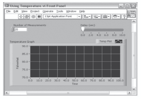
The front panel can include knobs, push buttons, graphs and various other controls (which are user inputs) and indicators (which are program outputs). Controls are inputs used to simulate instrument input devices and supply data to the block diagram of the VI, and indicators are outputs displays used to simulate instrument output devices and display data the block diagram acquires or generates. The front panel is customized to emulate control panels of traditional instruments, create custom test panels, or visually represent the control and operation of processes.
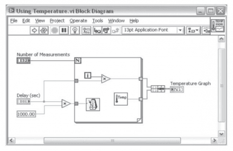
Block Diagram Windows
The block diagrams accompany the program for the front panel. Front panel objects appear as terminals on the block diagram and the components wired together. After the front panel is built, codes are added using graphical representations of functions in the block diagram to control the front panel objects. The block diagram contains the graphical source code composed of nodes, terminals, and wires. The block diagram is the actual executable program as shown in Figure 2.2.
[Related Article: Block Diagram in LabVIEW]
The components of a block diagram are lower-level VIs, built-in functions, constants and program execution control structures. Wires have to be drawn to connect the corresponding objects together to indicate the flow of data between each of them. Front panel objects have analogous terminals on the block diagram so that data can pass easily from the user to the program and back to the user. Use Express VIs, standard VIs and functions on the block diagram to create our measurement code.
Block diagram objects include the terminals, subVIs, functions, constants, structures and wires. LabVIEW is the easiest, most powerful tool for acquiring, analyzing and presenting real-world data. Terminals are entry and exit ports that exchange information between the panel and the diagram. Terminals are analogous to parameters and constants in text-based programming languages. Right-click the block diagram objects and select View As icon to change the icon view.
Icon/Connector Pane
To use a VI as a subVI, it must have an icon and a connector pane. Every VI displays an icon in the upper-right corner of the front panel and block diagram windows. An icon is a graphical representation of a VI. The icon can contain both text and images. To use a VI as a subVI, you need to build a connector pane. The connector pane is a set of terminals that correspond to the controls and indicators of that VI.
Control Palette of Front Panel in LabVIEW
Front Panel—Controls Palette
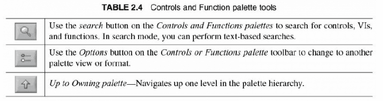
The Controls palette shown in the Figure is available only on the front panel. The Controls palette contains the controls and indicators which you can use to create the front panel. The Controls palette can be accessed from the front panel by selecting View» Controls Palette or by right-clicking an open space on the front panel window to display the Controls palette.
The Controls palettes contain sub-palettes of objects which you can use to create a VI. When you click a subpalette icon, the entire palette changes to the subpalette you selected. To use an object on the palettes, click the object and place it on the front panel.
[Related Article: Front Panel Controls and Indicators]

Table 2.4 lists the tools available in the toolbar of the Controls and Function palettes.
Block Diagram of Toolbar in LabVIEW
BLOCK DIAGRAM TOOLBAR
The Block diagram contains the graphical source code of a LabVIEW program. The concept of the block diagram is to separate the graphical source code from the user interface in a logical and simple manner. Front panel objects appear as terminals on the block diagram. Terminals on the block diagram reflect the changes made to their corresponding front panel objects and vice versa.
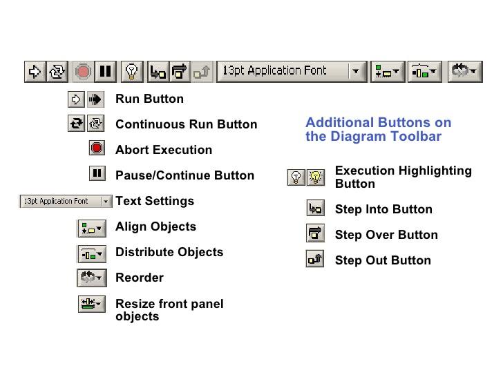
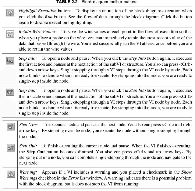
Table 2.2 provides the details of the block diagram toolbar buttons. Click the following buttons on the block diagram toolbar to debug the VI.
Block Diagram Objects and Environment
Block diagram objects include terminals, subVIs, functions, constants, structures, and wires that transfer data among other block diagram objects. You can use LabVIEW tools to create, modify, and debug a VI. A tool is a special operating mode of the mouse cursor, so the operating mode of the cursor corresponds to the icon of the tool selected.
LabVIEW chooses which tool to select based on the current location of the mouse. You can manually choose the tool you need by selecting it on the Tools palette (from the menu bar, select View» Tools Palette). Now you can choose your desired tool, which remains selected until you choose another tool from the Tools palette.
VI Toolbar - Use the buttons on the VI toolbar to run VIs, pause VIs, abort VIs, debug VIs, configure fonts, and align, group, and distribute objects.
LabVIEW Menus
Shortcut Menus
All LabVIEW objects have associated shortcut menus. To access the shortcut menu right-click the object and change the look or behavior of the front panel and block diagram objects. The most often-used menu is the object shortcut menu. All LabVIEW objects and empty space on the front panel and block diagram have associated shortcut menus.
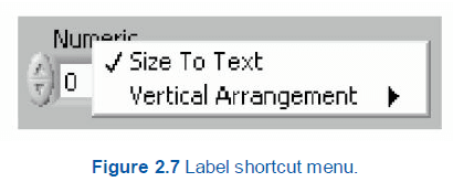
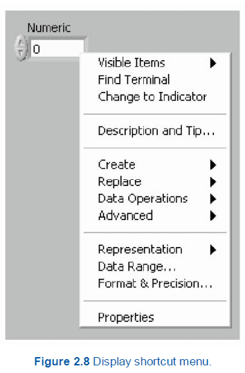
Use the shortcut menu items to change the look or behavior of the front panel and block diagram objects. To access the shortcut menu, right-click the object, front panel, or block diagram. To access the shortcut menu, right-click the object. Right-click the label as shown in Figure 2.7 to access its shortcut menu for front panel objects. Right-click the digital display to access its shortcut menu as shown in Figure 2.8. The shortcut menu for a meter is shown in Figure 2.9.
You can use the shortcut menu to create constants, controls, and indicators. Right-click a functioning terminal and select Create» Constant, Create» Control, or Create» Indicator from the shortcut menu to create. To replace nodes, right-click the node and select Replace from the shortcut menu.
LabVIEW VI Library
How do I Create LabVIEW VI Library
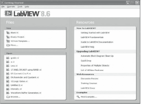
When you launch LabVIEW, the Getting Started window appears as shown in Figure 2.3. You can begin in LabVIEW by starting from a blank VI or project, opening an existing VI or project and modifying it, or opening a template from which to begin your new VI or project.
[Related Article: Creating SUBVIS From Sections Of A VI in Modular Programming]
To open a new project from the Getting Started window, select the Empty Project option. A new, unnamed project opens, and you can add files to and save the project.
To open a new, blank VI that is not associated with a project, select the Blank VI option on the Getting Started window. A blank VI opens a blank front panel and blank block diagram.
To Create a VI or Project from a Template select File»New to display the New dialog box, which lists the built-in VI templates. You also can display the New dialog box by clicking the New link in the Getting Started window.
To open an existing VI select the Browse option in the Getting Started window to navigate to and open an existing VI.
The menus at the top of a VI window contain items common to other applications, such as Open, Save, Copy and Paste, and other items specific to LabVIEW. To save a new VI, select File»Save. If you have already saved your VI, select File»Save As to access the Save As dialog box to create a copy of the VI, or delete the original VI and replace it with the new one.
VI Properties Dialog Box – LabVIEW
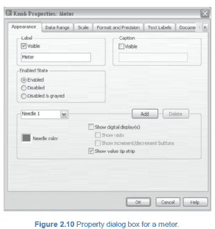
Property Dialog Boxes
Front panel objects also have property dialog boxes that you can use to change the look or behavior of front panel objects. Right-click the front panels object and select Properties from the shortcut menu to access the property dialog box for an object. Figure 2.10 shows the property dialog box for a meter. The options available on the property dialog box for an object are similar to the options available on the shortcut menu for that object.
Build a VI Front Panel, Icon and Connector Modular Programming - LabVIEW
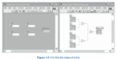
Build A Vi Front Panel And Block Diagram
The first step is to create the front panel and block diagram of a VI as shown in Figure 3.4. Consider a VI slope (m).vi to find the slope m given the coordinates y1, y2, x1, x2 of a line. The slope m = (y2 – y1)/(x2 – x1)?
[Related Article: Programming language used in LabVIEW]
Icon And Connector Pane
After you build a VI, build the icon and the connector pane so that you can use the VI as a subVI. The icon and connector pane correspond to the function prototype in text-based programming languages. Every VI displays an icon in the upper-right corner of the front panel and block diagram windows. An icon is a graphical representation of a VI. If you use a VI as a subVI, then the icon identifies the subVI on the block diagram of the VI.
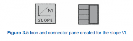
The default icon can be changed to a custom icon that contains text, images, or a combination of both. Figure 3.5 shows the custom icon and connector pane created for the VI to find the slope of a given line. The icon for slope VI contains text and images while the connector has four inputs (y1, y2, x1, x2) and one output (m). To create a subVI, you need to build an icon and a connector pane.
Create an Icon in Modular Programming - LabVIEW
Create Custom Icon
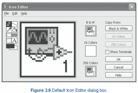
The default icon of a VI contains a number that indicates how many new VIs you have opened since launching LabVIEW. You can create custom icons to replace the default icon by completing the following steps:
- Right-clicking the icon in the upper-right corner of the front panel or block diagram and select Edit Icon from the shortcut menu to display the Icon Editor dialog box as shown in Figure 3.6.
1. Double-click the hatched box which will select the entire icon. Delete the selected portion.
2. Double-click the rectangular box which will create a border for the icon.
3. Use the line/pencil tool to draw.
4. Double-click the Edit Text tool ‘A’ to edit the required text.
5. Choose the Text Tool Font to edit font, font size, color and alignment of the text.
6. Use the Select Color tool to choose the background color of the icon.
7. Use the Fill With Color tool to change the background color of the icon.
8. Click OK to save the icon.
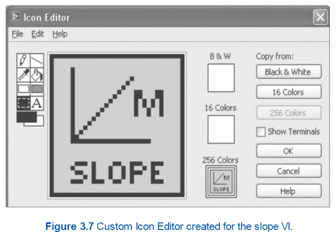
Using the tools on the icon editor, Figure 3.7 shows the custom Icon created for the slope VI. Use the Edit menu to cut, copy and paste images from and to the icon. When you select a portion of the icon and paste an image, LabVIEW resizes the image to fit into the selection area.
You also can drag a graphic from anywhere in the file system and place it in the upper-right corner of the front panel. LabVIEW converts the graphic to a 32×32 pixel icon. Depending on the type of monitor you use, you can design a separate icon for monochrome, 16-color and 256-color mode. Use the Copy from option on the right side of the Icon Editor dialog box to copy from a color icon to a black-and-white icon and vice versa.
After you select a Copy from option, click the OK button to complete the change. Figure 3.7 shows the custom icon created for the VI which finds the slope of a line.
LabVIEW Documentation Resources and Shortcut Keyboard Manual
Labview Documentation Resources
The programmer can use the Context Help window, the LabVIEW Help, and the NI Example Finder to help build and edit VIs. The Context Help window displays basic information about LabVIEW objects when you move the cursor over each object.
To toggle the display of the Context Help window, select Help» Show Context Help, press or click the Show Context Help Window button on the toolbar. The LabVIEW Help contains detailed descriptions of most palettes, menus, tools, VIs, and functions.
The LabVIEW Help also includes step-by-step instructions for using LabVIEW features. Access LabVIEW Help by the following methods:
-
Click the More Help button in the Context Help window
-
Select Help» Search the LabVIEW Help
-
Use the Click here for more help link in the Context Help window
-
Right-click an object and select Help
The New dialog box contains many LabVIEW template VIs that you can use to start building VIs. However, these template VIs are only a subset of the hundreds of example VIs included with LabVIEW. You can modify any example VI to fit an application, or you can copy and paste from an example into a VI that you create.
In addition to the example VIs that ship with LabVIEW, you also can access hundreds of example VIs on the NI Developer Zone at ni.com/zone. To search all examples using LabVIEW VIs, use the NI Example Finder. The NI Example Finder is the gateway to all installed examples and the examples located on the NI Developer Zone. To launch the NI Example Finder, select Help» Find Examples from the front panel or block diagram menu bar. You also can launch the NI Example Finder by clicking the arrow on the Open button on the LabVIEW dialog box and selecting Examples from the shortcut menu.
Keyboard Shortcuts
Frequently used Menu options have equivalent keyboard shortcuts:
-
Save a VI
-
Run a VI
-
Toggle between the front panel and block diagram.
-
Activate Context Help window.
-
Remove all broken wires.
-
Find object
-
Right-click to access Tools Palette
-
Press the key while using the positioning tool to click and drag a selection to duplicate an object.
LabVIEW Structure
Structure Tunnels
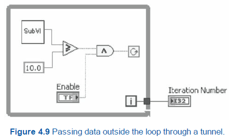
Data can be passed out of or into a loop through a tunnel. Tunnels feed data into and out of structures. The tunnel appears as a solid block on the border of the loop. The block is the color of the data type wired to the tunnel. Data passes out of a loop after the loop terminates.
[Related Article: Structures In Labview]
When a tunnel passes data into a loop, the loop executes only after data arrives at the tunnel. In Figure 4.9, the iteration terminal is connected to a tunnel. The value in the tunnel does not pass to the Iteration Number indicator until the While Loop has finished execution. Only the last value of the iteration terminal displays in the Iteration Number indicator.
Terminals Inside Or Outside Loops
Inputs pass data into a loop at the start of loop execution. Outputs pass data out of a loop only after the loop completes all iterations. If you want the loop to check the value of a terminal for each iteration, place the terminal inside the loop.
When you place the terminal of a front panel Boolean control inside a While Loop and wire the terminal to the conditional terminal of the loop, the loop checks the value of the terminal for every iteration to determine if it must iterate. You can stop the While Loop as shown in Figure 4.10(a) by changing the value of the front panel control to FALSE.
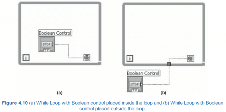
If you place the terminal of the Boolean control outside the While Loop as shown in Figure 4.8(b), and the control is set to FALSE if the conditional terminal is Stop if True when the loop starts, you cause an infinite loop. You also cause an infinite loop if the control outside the loop is set to TRUE and the conditional terminal is Continue if True.
Changing the value of the control does not stop the infinite loop because the value is only read once before the loop starts. To stop an infinite loop, you must abort the VI by clicking the Abort Execution button on the toolbar.
Labview functions palette
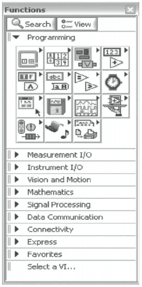
Use the Functions palette to create the block diagram. The Functions palette as shown in Figure 2.6 contains the sub-VIs, functions, and constants that are available only on the block diagram.
You can access the Functions palette from the block diagram by selecting View» Functions Palette. You can also right-click an open space on the block diagram to display the Functions palette. The VIs and functions located on the Functions palette depend on the palette view currently selected. The VIs and functions are located on sub-palettes based on the types of VIs and functions.
Opening Editing Saving and Placing SUBVIS on Block Diagram in Modular Programming
Opening And Editing Subvis
When you double-click a subVI, a front panel and a block diagram appear, rather than a dialog box in which you can configure options. The subVI controls and indicators receive data from and return data to the block diagram of the calling VI.
Click the Select a VI icon or text on the Functions palette, navigate to and double-click a VI, and place the VI on a block diagram to call a created subVI.
Complete the following steps to open a subVI and edit it.
- Step 1: Use the operating or positioning tool to double-click the subVI on the block diagram. LabVIEW displays the front panel of the subVI.
- Step 2: You also can press the key and use the operating or positioning tool to double-click the subVI on the block diagram to display the block diagram and front panel of the subVI.
- Step 3: For Mac OS press the key and for Linux press the key.
- Step 4: Edit the subVI.
[Related Article:Creating SUBVIS From Sections Of A VI in Modular Programming]
Placing Subvis On Block Diagrams
Complete the following steps to place a subVI on the block diagram.
-
Step 1: Display the block diagram of a new or existing VI by selecting Window» Show Block Diagram.
-
Step 2: If necessary, display the Functions palette by selecting View» Functions Palette.
-
Step 3: Click the Select a VI icon on the Functions palette.
-
Step 4: Navigate to and double-click the VI you want to use as a subVI, and place it on the block diagram.
-
Step 5: Wire the subVI terminals to other nodes on the block diagram.
Saving SUBVIS
Select File»Save to save a VI. You can save VIs as individual files or you can group several VIs together and save them in an LabVIEW Library (LLB). LLB files end with the extension .llb. National Instruments recommends that we save VIs as individual files, organized in directories, especially if multiple developers are working on the same project.
Displaying Sub VIS and Express VIS as Expandable Nodes in Modular Programming - LabVIEW
Overview on Displaying Sub VIS
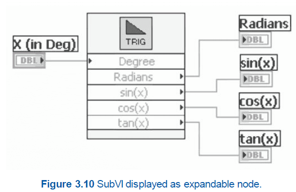
You can display a subVI as icons or as an expandable node. Expandable nodes appear as icons surrounded by a colored field. Expanded nodes of SubVIs appear with a yellow field. Use icons if you want to conserve space on the block diagram. Use expandable nodes to make wiring easier and to aid in documenting block diagrams.
By default, subVIs appear as icons on the block diagram. To display a subVI as an expandable node, right-click the subVI and remove the checkmark next to the View As Icon shortcut menu item. Figure 3.10 shows the expandable node of the trigonometry subVI. If you display a subVI as an expandable node, you cannot display the terminals for that node and you cannot enable database access for that node.
When you resize an expandable subVI, the input and output terminals of the subVI appear below the icon. Optional terminals appear with gray backgrounds. Recommended or required input or output terminals you do not display appear as input or output arrows in the colored field that surrounds the subVI icon.
If you wire to an optional terminal when the subVI is expanded, then resize the subVI so the optional terminal no longer appears in the expanded field, the optional terminal appears as an input or output arrow in the colored field. However, if you unwire the optional terminal, the input or output arrow does not appear.
Expandable Nodes in Modular Programming
By default, inputs appear above outputs when you expand the subVI. Right-click a terminal in the expandable field and select Select Input/Output from the shortcut menu to select an input or output to display.
A line divides inputs from outputs in the shortcut menu. Labels for expandable subVIs appear in the colored field that surrounds the icon. To resize the expandable node so that it accommodates the name of each terminal on a single line in the expandable field, right-click the subVI and select Size to Text from the shortcut menu.
 On-Job Support Service
Online Work Support for your on-job roles.

Our work-support plans provide precise options as per your project tasks. Whether you are a newbie or an experienced professional seeking assistance in completing project tasks, we are here with the following plans to meet your custom needs:
- Pay Per Hour
- Pay Per Week
- Monthly
| Name | Dates | |
|---|---|---|
| LabVIEW Training | Aug 04 to Aug 19 | View Details |
| LabVIEW Training | Aug 08 to Aug 23 | View Details |
| LabVIEW Training | Aug 11 to Aug 26 | View Details |
| LabVIEW Training | Aug 15 to Aug 30 | View Details |

Technical Content Writer


